Yet, this method was
time consuming and proved difficult for use among the general
population of physicians performing tracheostomy.
(Epstein, 2005) Specifically, inappropriately high, non-uniformly distributed, and a non-uniform dilation force throughout the procedure, as in CBR, is thought to result in anterior
tracheal wall compression and / or ring fracture further resulting in subglottic suprastomal
stenosis.
(Raghuraman, 2005) PDT subglottic
stenosis is typically displayed sooner and located in the suprastomal region, i.e. the region above the dilatational ostomy /
stoma, which typically has a smaller
diameter, around 17 mm compared to 25 mm, and thus may be more prone to negative clinical outcomes.
Although this adds the possible benefit to allow for greater handling and to improve the standing posture of the provider while performing PDT, such improvements do little to reduce the risks of
traumatic injury to the patient that can result directly from the shape and dilatational profile of the device.
The lack of modification(s), and adoption of devices thereof, to the fundamental shape and dilatational profile of PDT dilators may be due to the sophisticated, complex, and patient-specific nature of the neck
anatomy.
Although, the constant oval cross-sectional profile of the ATD is a drawback to its design, as it may lead to difficulty producing an accurate sized
stoma to insert most commonly used trachesostomy tube products that bear clearance profiles with a circular cross-section.
This dilation inevitably results in insufficiently dilated half-ovaloid cross-sectional areas on the superior and inferior edges of the tracheal
smooth muscle, cartilaginous rings, and pretracheal
fascia in addition to unnecessary overdilated areas transverse to the ostomy.
This increased compressive force can result in
tracheal ring fracture upon eventual access of the
airway as well as
posterior wall perforation immediately after passing the tracheal rings due to sudden loss of resistance.
Conversely, too little overdilation may result in higher risk of tracheal damage as discussed above when introducing the tracheostomy tube.
The overdilation of the ATD technique may not be applicable to smaller patients who cannot sustain such an increase in
transverse diameter and may not be applicable to operators without the procedural experience necessary to understand the proper “ostomy” size and geometry to optimize procedural results.
(Breatnach, Abbott, & Fraser, 1984; Griscom & Wohl, 1986) These rare patients may not be able to tolerate wholly transverse-biased dilation devices such as the ATD.
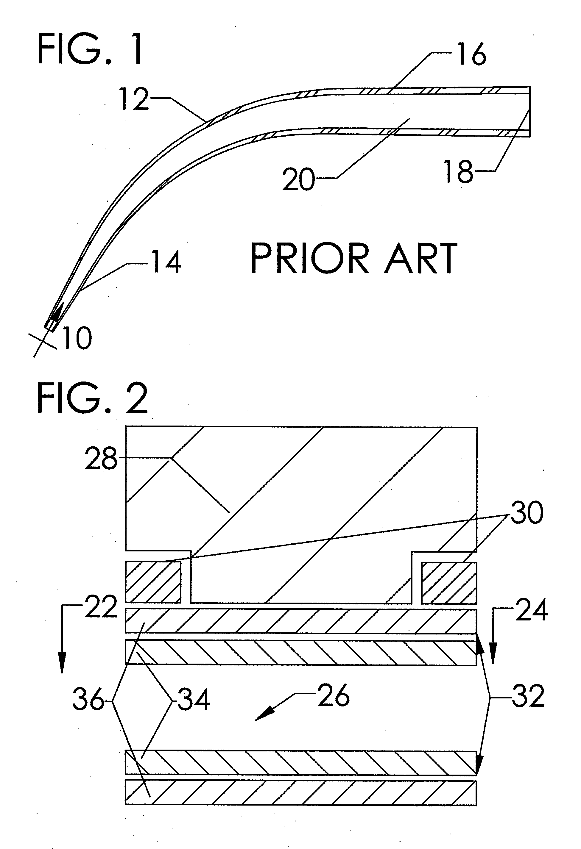
Although CBR-like, single-pass continuously tapered curved, dilators currently produced for performing PDT are relatively easy to use and inexpensive to manufacture, they are not without their drawbacks.
Clinically, there remain tremendous risks of unintended trauma to the patient receiving these interventions
ranging from minor short term complications to severe and potentially costly long-term complications and these risks arise from a low level of specialized design specificity for procedural effectiveness as well as end-user ergonomics as discussed prior.
As it relates to the production of single-pass dilators for use in performing PDT, these issues result in an inferiorly specified product that is ill suited for
insertion into the specific tissue types encountered during this procedure.
Additionally, the past manufacturing methods do not allow for the generation of clinically relevant device modifications for the unique anatomy of specific patients.
Thus, these simple devices continue to cause
traumatic injury to patients and present
undo risk for physicians to adopt this clinically effective and tremendously cost-beneficial procedure.
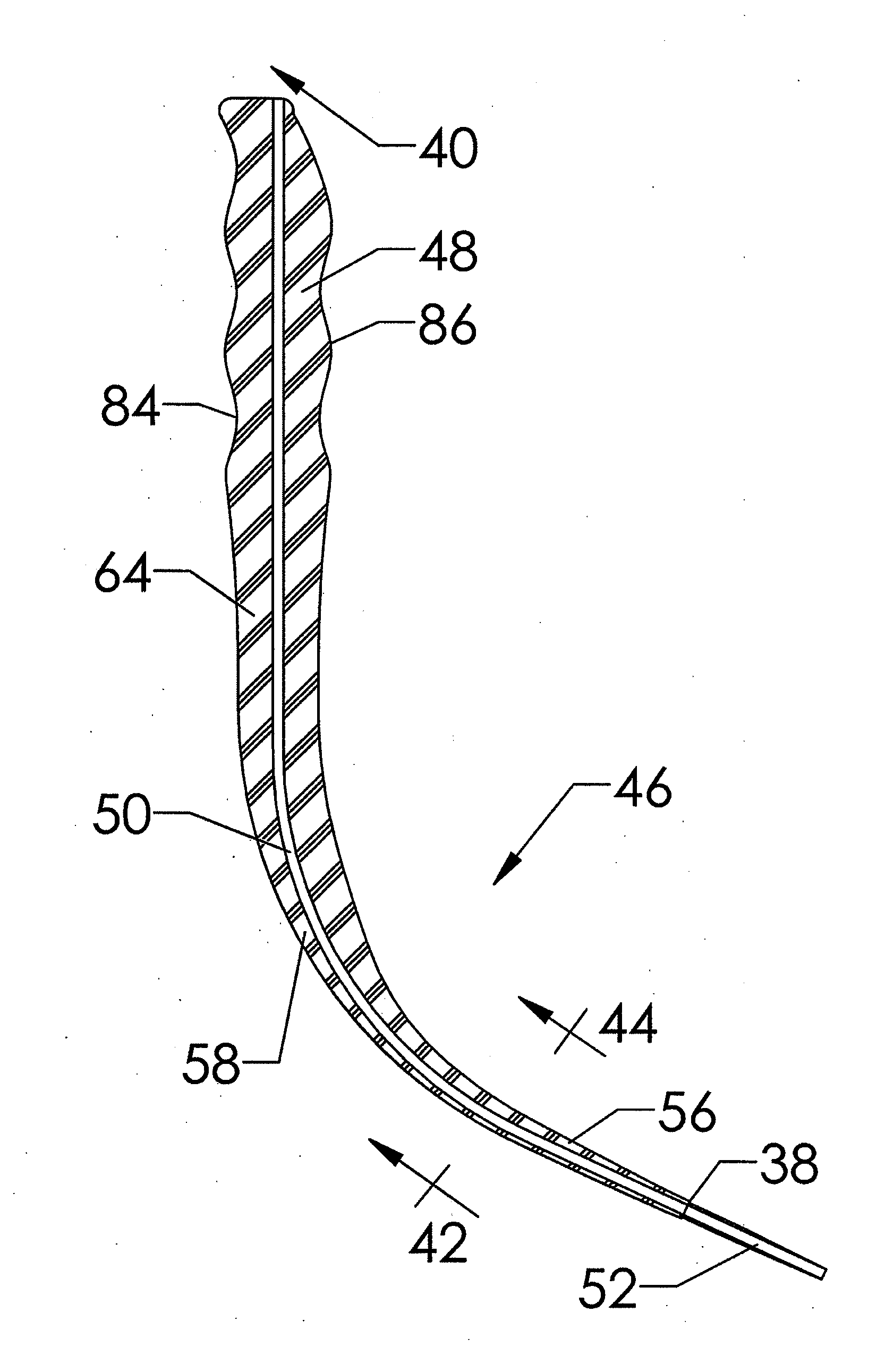
(a) Their use results in the generation of both compressive and torque dilation forces on the trachea, specifically on the adjacent superior tracheal ring, caused by their generally curved dilation profiles that bear a continuous, increasing taper;
(b) The geometric profile of the curved tapered dilators commonly used in PDT results in the generation of, relatively, high dilatational force. This high level of force often occurs while the
dilator is separating the pretracheal
fascia due to the large cross-sectional profiles of the portion of the curved dilator in contact with the pretracheal
fascia proximal to the portion of the dilator in contact with the tracheal
smooth muscle and cartilaginous rings. This force is transferred to the cartilaginous rings of the trachea, specifically the adjacent superior tracheal ring, and induces tracheal ring fractures that may lead to subsequent complications including tracheal stenosis;
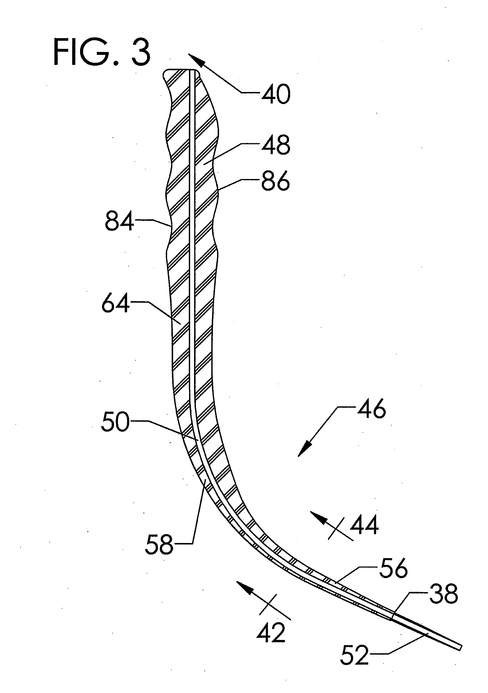
(c) The simple tapered circular geometry of the cross-sectional profile of PDT dilators fail to separate the adjacent stomal tracheal rings by transverse dilation prior to inducing the previously stated high dilatational force on the pretracheal fascia. This failure to perform transverse dilation prior to dilating in the longitudinal direction may specifically lead to subglottic suprastomal tracheal stenosis arising as a consequence of placement of a force capable of fracturing the adjacent superior tracheal ring;
(d) The isotropic or circularly symmetric cross-sectional dilatational profile of PDT dilators results in the generation of a non-uniform dilation force while passing through the varying
layers of tissue impacted by tracheostomy producing a higher level of stress in the longitudinal, i.e. superior-inferior, direction of the cartilaginous ring and tracheal smooth
muscle tissues.
(e) A generally convex, i.e. curved or circular, geometric profile on the superior and inferior dilatational profiles of PDT dilators cause a non-uniform distribution of force, specifically compressive force, upon the curved surface of the adjacent superior cartilaginous tracheal ring. This compressive force may cause tracheal ring fracture on the most anterior-medial aspect of the ring leading potentially to subsequent complications, including tracheal stenosis; and

