Ion implantation apparatus and control method thereof

a technology of ion implantation and control method, which is applied in the direction of electrical apparatus, irradiation devices, electric discharge tubes, etc., can solve the problems of beam current control using beam measurement and scanning control, beam measurement within scanning, and beam measurement at a position on a side opposite to the one side of the ion implantation position, etc., to achieve high reproducibility and facilitate tuning. , the effect of high reproducibility

Active Publication Date: 2013-10-03
SENCORP
View PDF1 Cites 19 Cited by
  • Summary
  • Abstract
  • Description
  • Claims
  • Application Information

AI Technical Summary

Benefits of technology

[0110]In the present invention, the movable or stationary beam measuring device is disposed at an arbitrary position of the ion implantation position, and a beam-scanned beam waveprofile is obtained through an AD converter such as an oscilloscope. Accordingly, the beam waveprofile may be measured at a high speed. Beam tuning is performed with both of the measured beam waveprofile and the beam current set as a reference, and thus the beam residual phenomenon does not occur. Not only the amount of the beam current but also spreading of the beam may be simultaneously tuned, and thus both of these may be tuned with high reproducibility.
[0111]Acc

Problems solved by technology

However, in the above-described beam current control method, since the one side beam current measuring instrument is disposed in a stationary manner, it is impossible to perform beam measurement at a position on a side opposite to the one side of the ion implantation position, and beam measurement within a scanning range of the ion implantation position.
Therefore, the beam current control using the beam measurement and the scanning control may be limited, and thus this limitation becomes a cause of obstruction to the request for measurement with high precision.
However, in this beam measurement method, it is impossible to perform beam measurement at a position on a side opposite to the one side of the ion implantation position, and beam measurement within the scanning range of the ion implantation position.
Therefore, the beam measurement may be limited, and thus this limitation becomes a cause of obstruction to the request for the high precision of the beam current control using the beam measurement and the scanning control.
This method does not consider performing measurement of an ion beam, which is incident

Method used


Image

  • Ion implantation apparatus and control method thereof
  • Ion implantation apparatus and control method thereof
  • Ion implantation apparatus and control method thereof

Examples


Embodiment Construction

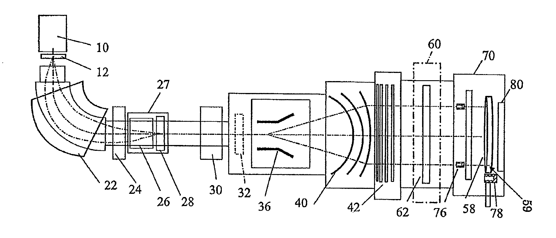
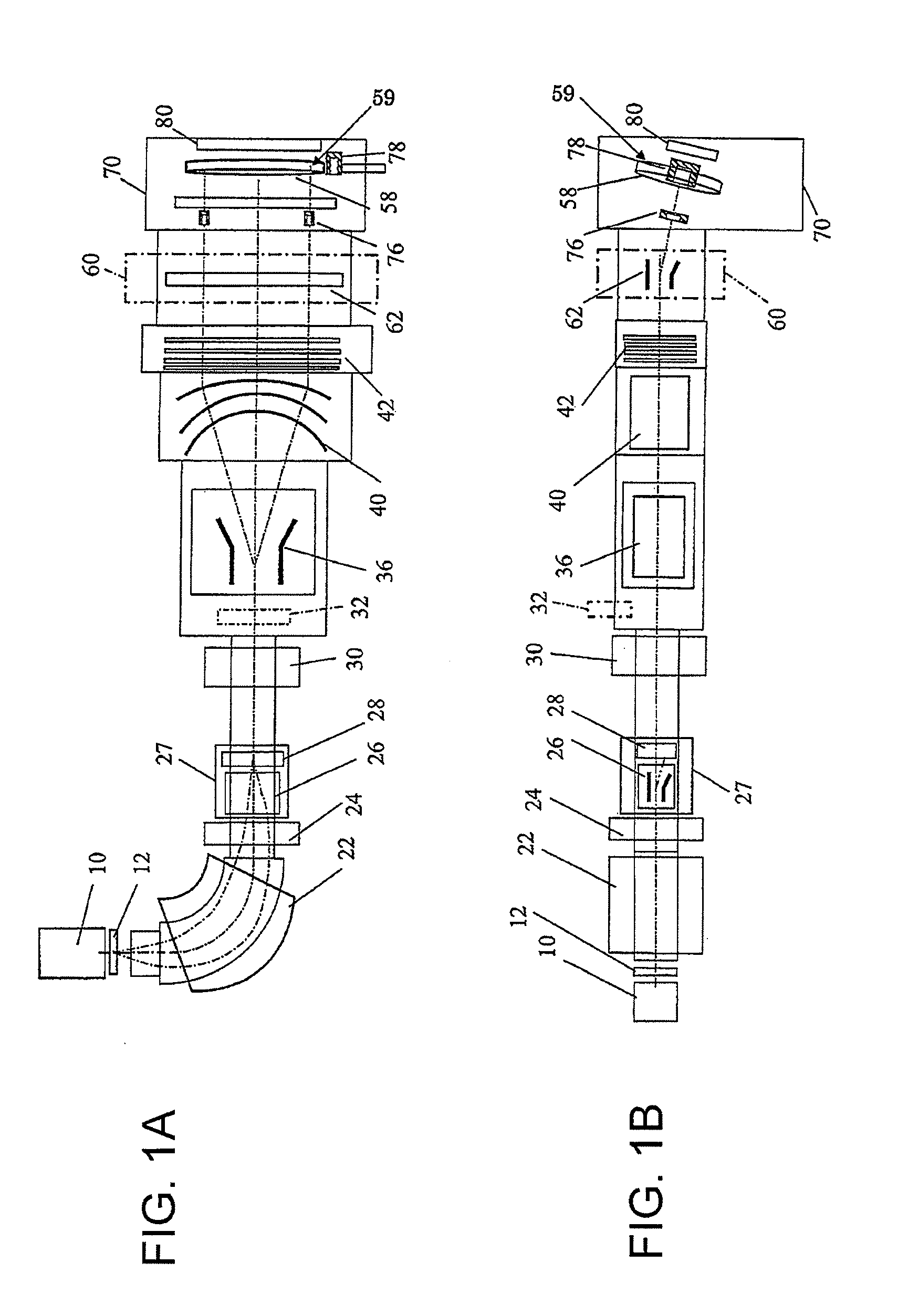
[0129]A schematic configuration of an ion implantation apparatus to which the present invention is applied will be described with reference FIGS. 1A and 1B. The ion beam implantation apparatus to which the present invention is applied has a configuration in which an ion beam extracted from an ion source 10 by an extraction electrode 12 is allowed to pass through a beam line that reaches a wafer 58, and a mass-analyzing magnet unit 22, a mass-analyzing slit 28, a beam scanner 36, and a wafer processing chamber (ion implantation chamber) 70 are disposed along the beam line. A wafer mechanical scanning device (mechanical Y-scanning device) provided with a wafer supporting platen that supports the wafer 58 is disposed in the wafer processing chamber 70. The ion beam extracted from the ion source 10 is guided along the beam line to the wafer 58 on the wafer supporting platen that is disposed at an ion implantation position of the wafer processing chamber 70. At a section of the beam line...


PUM


Abstract

A vertical profile, a horizontal profile, and an integrated current value of an ion beam are measured by a plurality of stationary beam measuring instruments and a movable or stationary beam measuring device. At a beam current adjustment stage before ion implantation, a control device simultaneously performs at least one of adjustment of a beam current to a preset value of the beam current, adjustment of a horizontal beam size that is necessary to secure uniformity of the horizontal ion beam density, and adjustment of a vertical beam size that is necessary to secure the uniformity of the vertical ion implantation distribution on the basis of a measurement value of the stationary beam measuring instruments and the movable or stationary beam measuring device.

Description

[0001]This application is based upon and claims the benefit of priority from Japanese Patent Application No. 2012-77101, filed on Mar. 29, 2012, the disclosure of which is incorporated herein in its entirety by reference.BACKGROUND OF THE INVENTION[0002]1. Field of the Invention[0003]The present invention relates to an ion implantation apparatus that is capable of implanting an ion beam extracted from an ion source into a wafer, and a control method thereof.[0004]2. Description of Related Art[0005]In general, an ion implantation apparatus has a configuration in which an ion source, an extraction electrode, a mass-analyzing magnet unit, a mass-analyzing slit, a beam scanner, a beam parallelizing device, an acceleration and deceleration device, an angular energy filter (AEF) device, a wafer processing chamber, a beam measuring device, and the like are disposed along a beam line. The ion implantation apparatus is used to implant ions into a wafer that is a semiconductor substrate using...

Claims


Application Information

Patent Timeline
IPC IPC(8): H01L21/67
CPCH01L21/67213H01J37/147H01L21/265H01J2237/24542H01J37/3171H01J2237/24521H01J2237/24535H01J37/304H01J37/153H01J37/317
Inventor KARIYA, HIROYUKIISHIKAWA, MASAKIINDA, YOSHIAKIKUROSE, TAKESHIYAGITA, TAKANORIYUMIYAMA, TOSHIO
Owner SENCORP
Why Eureka
Try Eureka