Protective circuit, battery charger, and power storage device

a technology of protective circuit and battery charger, which is applied in the direction of electric power, transportation and packaging, electric vehicles, etc., can solve the problem that the method is not suitable for a short-time power stop, and achieve the effect of reducing the power consumption of the protective circui

Active Publication Date: 2013-10-03
SEMICON ENERGY LAB CO LTD
View PDF12 Cites 16 Cited by
  • Summary
  • Abstract
  • Description
  • Claims
  • Application Information

AI Technical Summary

Benefits of technology

[0016]In particular, in the case of using the memory element in which supply, holding, and discharge of electric charge to, in, and from a capacitor or a floating node are controlled by a transistor with extremely low off-state current, data is written by supply of electric charge; th

Problems solved by technology

The data can be backed up in an external nonvolatile memory device such as hard disk or a flash memory; however, this method is not suitable for a short-time power stop

Method used


Image

  • Protective circuit, battery charger, and power storage device
  • Protective circuit, battery charger, and power storage device
  • Protective circuit, battery charger, and power storage device

Examples


embodiment 1

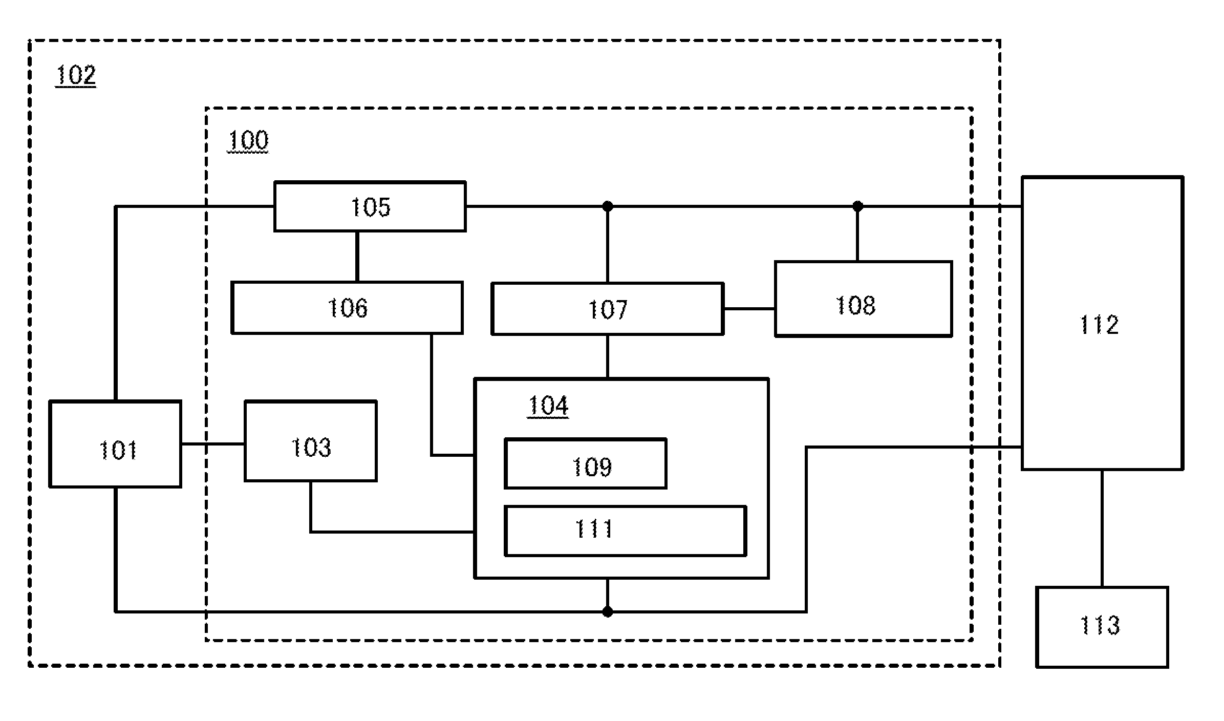
[0034]FIG. 1 is a block diagram illustrating an example of the structure of a protective circuit 100 and a power storage device 102 in one embodiment of the present invention. In block diagrams shown in this specification, components are classified according to their functions and shown as independent blocks; however, it is practically difficult to completely separate the components according to their functions, and one component may be related to a plurality of functions.

[0035]The protective circuit 100 illustrated in FIG. 1 includes a detection unit 103, a battery management unit (BMU) 104, a switch circuit 105, a switch control unit 106, a power switch 107, and a power controller 108. The power storage device 102 includes a secondary battery 101 in addition to the protective circuit 100.

[0036]As the secondary battery 101, a lead-acid battery, a nickel-cadmium battery, a nickel-hydride battery, or a lithium-ion battery can be used, for example.

[0037]The detection unit 103 has a fu...

embodiment 2

[0078]Next, as one embodiment of the present invention, an example of the structure of the buffer memory device 111 illustrated in FIG. 1 will be described. In one embodiment of the present invention, the buffer memory device 111 includes a plurality of unit memory circuits each having a combination of a volatile memory element and a memory element that can retain data for a period as long as 60 seconds or as short as several milliseconds after supply of the power supply voltage is stopped. FIG. 6 illustrates an example of a circuit diagram of a unit memory circuit 200.

[0079]The unit memory circuit 200 includes a first memory element 201, a second memory element 202, a switch 203, a switch 204, a switch 205, a logic element 206 that inverts the polarity of an inputted signal and outputs the inversion signal, and a capacitor 207. The first memory element 201 corresponds to the volatile memory element, which retains data only in a period during which the power supply voltage is suppli...

embodiment 3

[0145]FIG. 5 is a block diagram illustrating an example of the structure of the power controller 108. The power controller 108 includes an interface (IF) 300, a controller 301, a controller 302, a clock generator (CLK_GEN) 303, and a buffer 304.

[0146]The IF 300 has a function of converting the format of signals from the host system 112 and the processor 109 illustrated in FIG. 1 and a function of removing noise, for example.

[0147]The clock generator (CLK_GEN) 303 includes a frequency divider circuit 305 and has a function of generating a clock signal used in various circuits in the power controller 108, such as the IF 300, the controller 301, the controller 302, and the buffer 304, from a clock signal CLK input from the host system 112.

[0148]The controller 301 has a function of generating a reset signal (P_RESET), an interrupt signal (P_INT), and the like for the processor 109 from various signals such as a reset signal (RESET) and an interrupt signal (INT) input from the host syste...


PUM


Abstract

A low-power protective circuit includes a detection unit that intermittently detects a voltage across a secondary battery; a battery management unit that includes a buffer memory device and a processor and determines, based on a value of the voltage, whether the secondary battery needs to be charged; a switch circuit that establishes or breaks electrical continuity between a host system and the secondary battery; a switch control unit that turns on or off the switch circuit in accordance with the judgment made by the battery management unit; a switch that controls supply of power supply voltage from the secondary battery to the battery management unit; and a power controller that intermittently stops supply of the power supply voltage to the battery management unit by turning off the switch.

Description

BACKGROUND OF THE INVENTION[0001]1. Field of the Invention[0002]The present invention relates to a protective circuit for controlling charging of a secondary battery and a battery charger including the protective circuit. The present invention also relates to a power storage device including a secondary battery in addition to the protective circuit or the battery charger.[0003]2. Description of the Related Art[0004]Overcharge and overdischarge of secondary batteries such as lithium ion batteries not only shorten their life but also cause ignition due to internal short-circuit. For this reason, a battery charger (also referred to as charger) for charging a secondary battery often includes a circuit for preventing overcharge and overdischarge, which is called a charging control circuit or a protective circuit, in addition to a power supply circuit.[0005]The protective circuit recognizes the charging state of a secondary battery by monitoring a voltage across the secondary battery (a t...

Claims


Application Information

Patent Timeline
IPC IPC(8): H02J7/00
CPCH02J7/007
Inventor KOYAMA, JUN
Owner SEMICON ENERGY LAB CO LTD
Why Eureka
Try Eureka