
Production logging instrument

Active Publication Date: 2013-10-17
FASTCAP SYST
View PDF5 Cites 39 Cited by
  • Summary
  • Abstract
  • Description
  • Claims
  • Application Information

AI Technical Summary

Benefits of technology

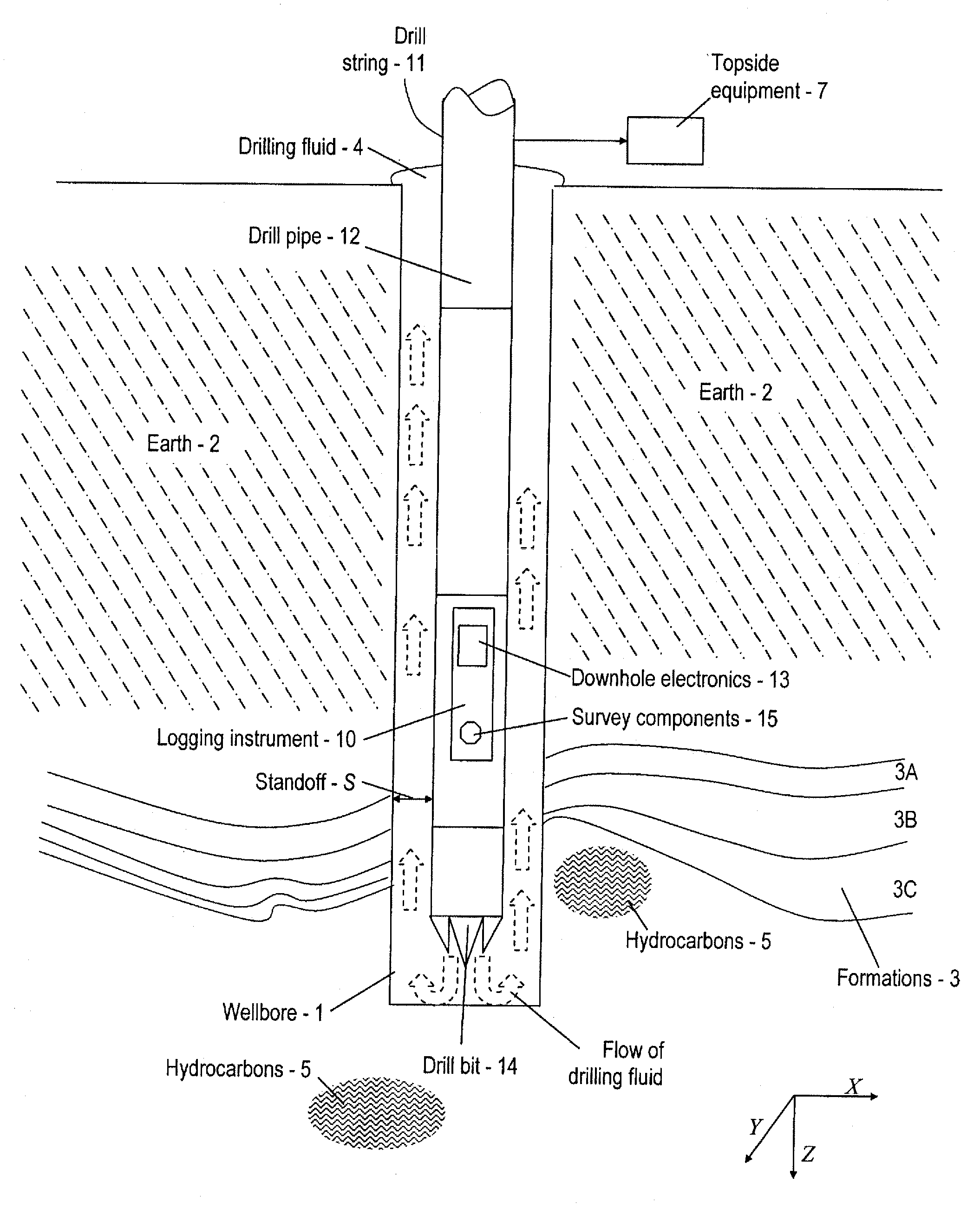
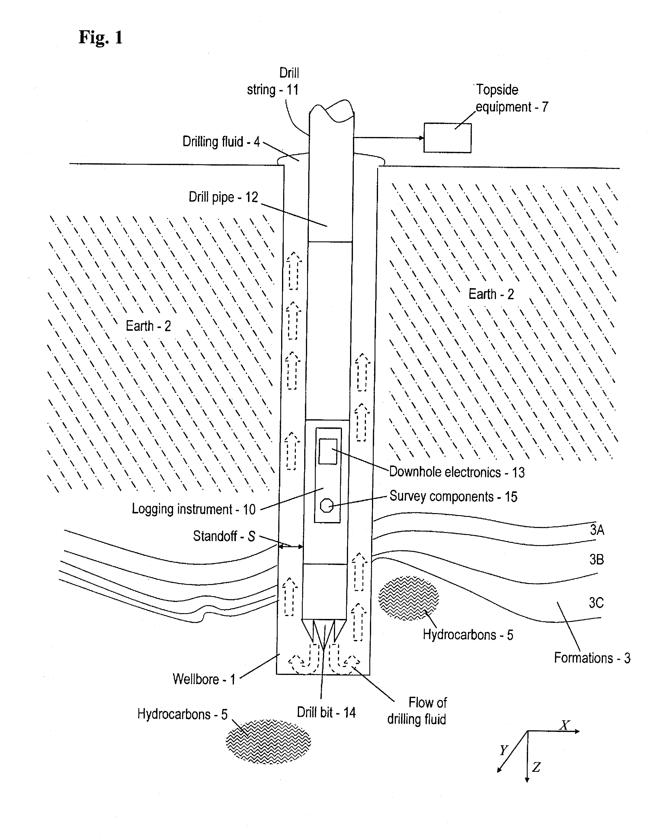
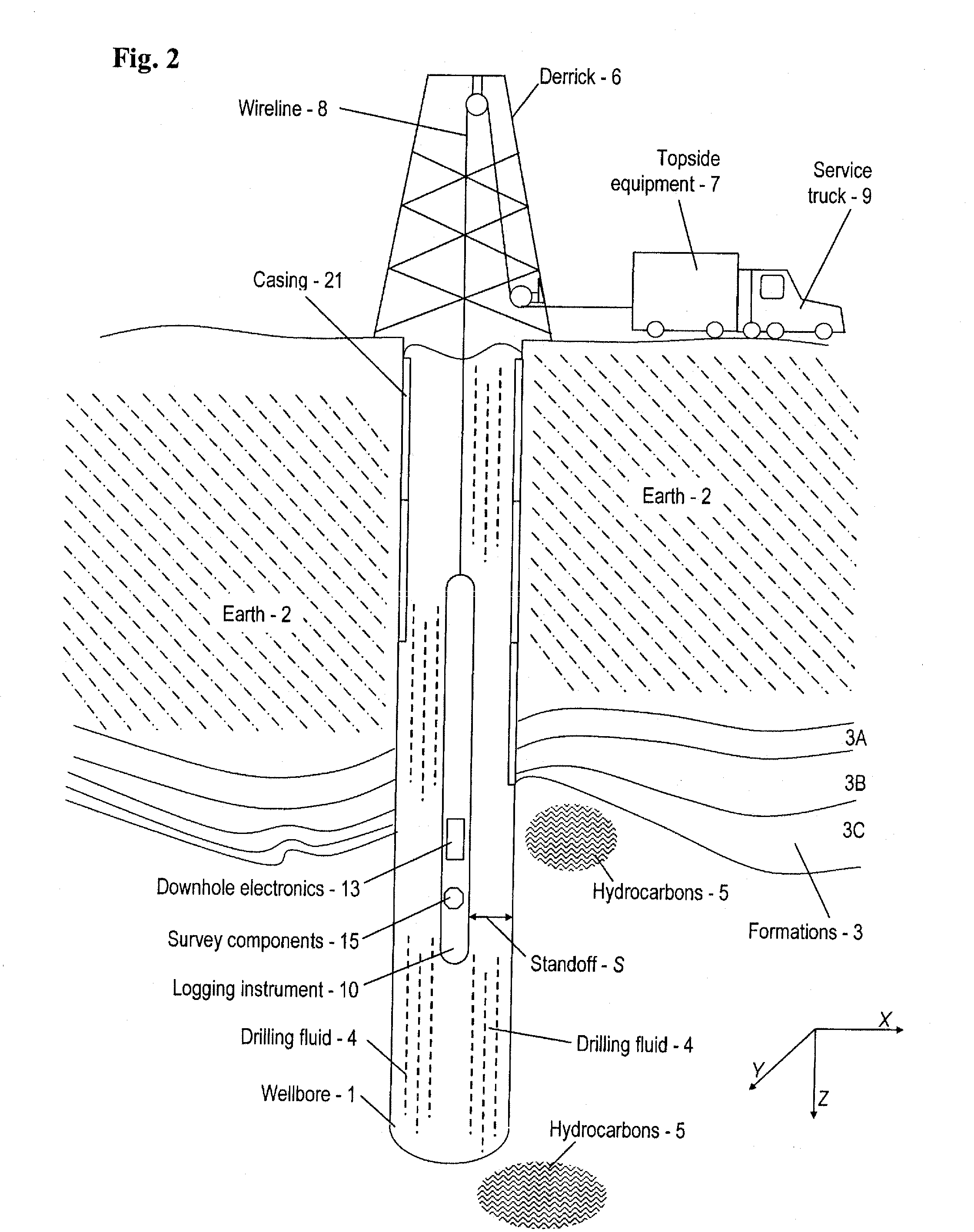
The patent describes a logging system for use in oil and gas wells that includes components such as surveying equipment, a communication channel, and downhole electronics powered by a power block. The power block is designed to provide power to the logging instrument for performing measurements downhole during production. The instrument uses a rechargeable energy storage, which can be trickle charged during a first time period and then used to operate the instrument during a second, shorter time period. The system can also include sensors and other tools to perform various logging operations. Additionally, the patent describes a distributed logging system with multiple logging instruments placed at different locations within a well. Overall, the patent focuses on the efficient and effective operation of a logging system in wellbores.

Problems solved by technology

Unfortunately, the various tools and instruments that are useful for well logging generally involve intricate equipment that requires a connection to a power supply and other ancillary equipment topside.
However, removing logging equipment from a well leaves operators in a situation where it is impossible to characterize the resources downhole.
Of course, cessation of production has a great financial impact on the operator.

Method used


Image

  • Production logging instrument
  • Production logging instrument
  • Production logging instrument

Examples


first embodiment

[0134]With regard to anions211 suited for use in an ionic liquid that provides the electrolyte 206, various organic anions 211 may be used. Exemplary anions 211 and structures thereof are provided in Table 1. In a first embodiment, (No. 1), exemplary anions 211 are formulated from the list of substitute groups (a) provided above, or their equivalent. In additional embodiments, (Nos. 2-5), exemplary anions 211 are formulated from a respective base structure (Y2, Y3, Y4, . . . Yn) and a respective number of anion substitute groups (α1, α2, α3, . . . αn), where the respective number of anion substitute groups (a) may be selected from the list of substitute (α) groups provided above, or their equivalent. Note that in some embodiments, a plurality of anion substitute groups (α) (i.e., at least one differing anion substitute group (a)) may be used in any one embodiment of the anion 11. Also, note that in some embodiments, the base structure (Y) is a single atom or a designated molecule (a...

second embodiment

[0272]Specific examples of glass-to-metal seals that have been used in the ultracapacitor 210 include two different types of glass-to-metal seals. A first one is from SCHOTT with a US location in Elmsford, N.Y. This embodiment uses a stainless steel pin, glass insulator, and a stainless steel body. A second glass-to-metal seal is from HERMETIC SEAL TECHNOLOGY of Cincinnatti, Ohio. This second embodiment uses a tantalum pin, glass insulator and a stainless steel body. Varying sizes of the various embodiments may be provided.

[0273]An additional embodiment of the glass-to-metal seal includes an embodiment that uses an aluminum seal and an aluminum body. Yet another embodiment of the glass-to-metal seal includes an aluminum seal using epoxy or other insulating materials (such as ceramics or silicon).

[0274]A number of aspects of the glass-to-metal seal may be configured as desired. For example, dimensions of housing and pin, and the material of the pin and housing may be modified as appr...


PUM


Abstract

A logging system and method for operating a logging system are typically used in a wellbore. The logging system may include a logging instrument including a rechargeable energy storage and logging electronics, and a cable configured to trickle charge the rechargeable energy storage. The rechargeable energy storage may include an ultracapacitor. The rechargeable energy storage may be trickle charged through the cable from a remote power source.

Description

CROSS REFERENCE TO RELATED APPLICATIONS[0001]This application claims priority based on Provisional Application No. 61 / 555,100 filed Nov. 3, 2011 and Provisional Application No. 61 / 624,080 filed Apr. 13, 2012, which are hereby incorporated by reference in their entirety.BACKGROUND OF THE INVENTION[0002]1. Field of the Invention[0003]The invention disclosed herein relates to exploration for oil and gas and, in particular, to a downhole instrument for production well-logging.[0004]2. Description of the Related Art[0005]In the exploration for oil and gas, it is necessary to drill a wellbore into the Earth. Evaluation of the Earth and the surrounding formations is often undertaken with the use of sophisticated tooling lowered into the wellbore. Evaluations, or well-logging, may be completed while drilling (measurement while drilling, (MWD or LWD)) or after drilling, such as by lowering of a wireline.[0006]A variety of instruments may be used. Instruments that are directed to technologies...

Claims


Application Information

Patent Timeline
IPC IPC(8): H02J7/00
CPCH02J7/0042G01V11/002E21B47/122E21B47/011E21B41/0085E21B47/017E21B47/13H01G11/08H01G11/14H01G11/28H01G11/04H01G2/106H01G2/10Y02E60/13E21B47/00E21B17/003E21B49/00H01G11/32H01G11/52H01G11/80H01M6/14H01M2220/10H02J7/0045H02J7/345
Inventor SIGNORELLI, RICCARDOCOOLEY, JOHN J.GREEN, MORRISTURNER, IRA M.MCGRATH, JENNAKUTTIPILLAI, PADMANABAN SASTHAN
Owner FASTCAP SYST
Learn More