Conductive metal ink composition, and method for preparing a conductive pattern

a technology of conductive metal and ink composition, which is applied in the direction of resistive material coating, inks, printing, etc., can solve the problems of reducing the economic efficiency of the whole process, reducing the surface characteristics of the conductive pattern and the physical properties of the final product, and achieving excellent attachment ability and improved conductivity

Active Publication Date: 2013-10-24
LG CHEM LTD
View PDF6 Cites 25 Cited by
  • Summary
  • Abstract
  • Description
  • Claims
  • Application Information

AI Technical Summary

Benefits of technology

[0011]According to the exemplary embodiments of the present invention, a conductive metal ink composition that is appropriately applied to a roll printing process so that a conductive pattern exhibiting

Problems solved by technology

However, in order to form a pattern by the photolithography, various processes such as coating, exposing, developing and etching of a photosensitive material should be performed, thereby making an entire diode manufacturing process complicated and largely reducing economic efficiency of the process.
Further, since the conductive metal comprised in the conductive ink composition has poor attachment ability to the board and is easily agglomerated in the firing process, surface characteristics of the conductive pattern and physical properties of

Method used


Image

  • Conductive metal ink composition, and method for preparing a conductive pattern
  • Conductive metal ink composition, and method for preparing a conductive pattern
  • Conductive metal ink composition, and method for preparing a conductive pattern

Examples


example

Example 1

Conductive Metal Ink Composition and Formation of Conductive Pattern

[0077]8.57 g of the silver nanoparticles having the average particle diameter of 50 nm, 2.3 g of methyl cellosolve (vapor pressure of 6.2 torr at 25° C.), 7 g of ethanol (vapor pressure of 59.3 torr at 25° C.), 10 g of butyl cellosolve (vapor pressure of 0.76 torr at 25° C.), 0.7 g of Tackirol 160, 0.2 g of BYK® 333 that was the silicon-based surfactant, 0.0857 g of the nickel nanoparticles having the average particle diameter of 100 nm, and 0.004 g of Disperbyk® 180 were mixed with each other, agitated for 24 hours, and filtered by the filter of 1 μm, thus manufacturing the ink composition. The initial viscosity of ink was measured by using the Brookfield viscometer, and as a result thereof, the viscosity was 3.2 cps.

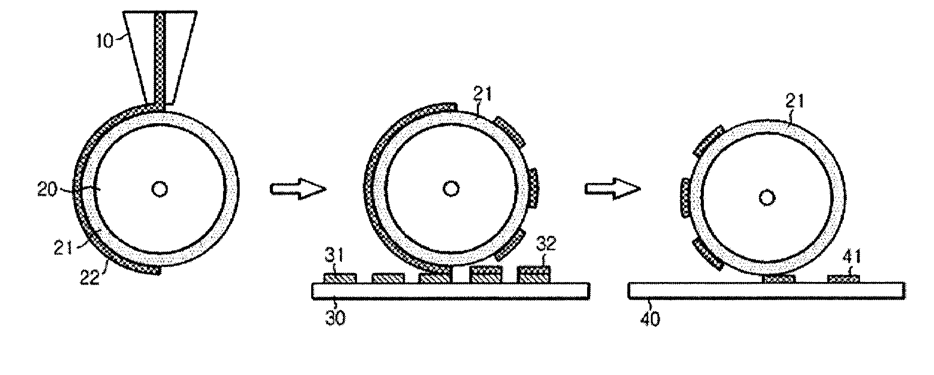
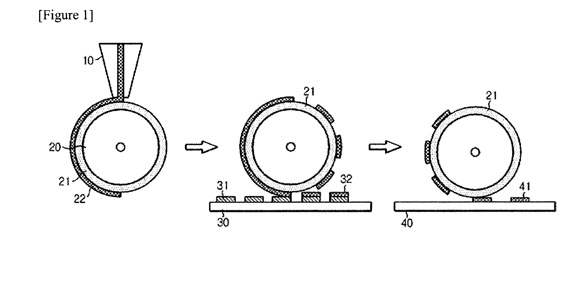
[0078]After the ink composition was coated on the PDMS blanket of the roller, the pattern of the ink composition was formed on the roller by contacting a cliche where the pattern corresponding...

example 2

[0079]8.57 g of the silver nanoparticles having the average particle diameter of 50 nm, 2.3 g of methyl cellosolve (vapor pressure of 6.2 torr at 25° C.), 7 g of ethanol (vapor pressure of 59.3 torr at 25° C.), 10 g of butyl cellosolve (vapor pressure of 0.76 torr at 25° C.), 0.7 g of Tackirol 160, 0.2 g of BYK® 333, 0.0857 g of the tin nanoparticles having the average particle diameter of 100 nm, and 0.01 g of tin(II) (2-ethylhexanoate) were mixed with each other, agitated for 24 hours, and filtered by the filter of 1 μm, thus manufacturing the ink composition. Thereafter, the conductive pattern was formed by using the same method as Example 1, and the physical properties were evaluated by using the same method as Example 1.

example 3

[0080]8.57 g of the silver nanoparticles having the average particle diameter of 50 nm, 2.3 g of methyl cellosolve (vapor pressure of 6.2 torr at 25° C.), 7 g of ethanol (vapor pressure of 59.3 torr at 25° C.), 10 g of butyl cellosolve (vapor pressure of 0.76 torr at 25° C.), 0.7 g of Tackirol 160, 0.8 g of BYK® 337, 0.0857 g of the magnesium oxide nanoparticles having the average particle diameter of 20 nm, and 0.005 g of Disperbyk® 180 were mixed with each other, agitated for 24 hours, and filtered by the filter of 1 thus manufacturing the ink composition. Thereafter, the conductive pattern was formed by using the same method as Example 1, and the physical properties were evaluated by using the same method as Example 1.


PUM

PropertyMeasurementUnit
Temperatureaaaaaaaaaa
Timeaaaaaaaaaa

Abstract

The present invention relates to a conductive metal ink composition, comprising: a first metal powder having conductivity; a non-aqueous solvent; an attachment improving agent; and a polymer coating property improving agent, and a method for forming a conductive pattern by using the conductive metal ink composition, and the conductive metal ink composition can be appropriately applied to a roll printing process and a conductive pattern exhibiting more improved conductivity and excellent attachment ability with respect to a board can be formed.

Description

TECHNICAL FIELD[0001]The present invention relates to a conductive metal ink composition and a method for forming a conductive pattern. More particularly, the present invention relates to a conductive metal ink composition that is appropriately applied to a roll printing process so that a conductive pattern exhibiting more improved conductivity and excellent attachment ability with respect to a board can be formed, and a method for forming a conductive pattern by using the same. This application claims priority from Korean Patent Application No. 10-2010-0083589 filed on Aug. 27, 2010 in the KIPO, the disclosure of which is incorporated herein by reference in its entirety.BACKGROUND ART[0002]Currently, various flat panel display diodes are widely used. In order to manufacture the flat panel display diode, various conductive patterns such as electrodes, wires, or electromagnetic wave blocking filters are formed on a substrate, and the most widely used process for forming these pattern...

Claims


Application Information

Patent Timeline
IPC IPC(8): C09D11/00H05K1/02
CPCC09D11/52H05K1/02C09D11/033C09D11/037H01B1/22H05K1/097H05K3/1275H05K2201/0272H05K2203/0534B41M1/00H05K3/10B05D5/12
Inventor SEONG, JIEHYUNJEON, KYOUNG SUHEO, SOO YEONLEE, JONG TAIKHWANG, JI YOUNGHWANG, IN-SEOKLEE, SEUNG-HEON
Owner LG CHEM LTD
Why Eureka
Try Eureka