Separator and electrochemical device having the same

a technology of separation device and separation electrode, which is applied in the manufacture of final product, cell component details, cell components, etc., can solve the problems of thermal runaway, complicated fabrication, safety problems of lithium ion batteries, etc., and achieves superior adhesiveness, good thermal safety, and reduced thickness

Active Publication Date: 2013-10-24
TORAY BATTERY SEPARATOR FILM +1
View PDF6 Cites 32 Cited by
  • Summary
  • Abstract
  • Description
  • Claims
  • Application Information

AI Technical Summary

Benefits of technology

[0019]The separator of the present invention can have good thermal safety due to a porous organic-inorganic coating layer formed on one surface thereof, and superior adhesiveness due to a porous coating layer made of a binder thin film formed by applying and drying a mixture of a binder polymer and a non-solvent on the other surface thereof. Also, the separator can have a decreased thickness to reduce the resistance of electrochemical device and improve the capacity thereof.

Problems solved by technology

However, such lithium ion batteries suffer from safety problems, such as fire and explosion, when encountered with the use of organic electrolytes and are disadvantageously complicated to fabricate.
Overheating of an electrochemical device may cause thermal runaway or a puncture of a separator may pose an increased risk of explosion.
This thermal shrinkage behavior may cause electrical short between a cathode and an anode.
However, if the porous organic / inorganic coating layer is formed on both surfaces of the porous substrate, the thickness of the separator becomes too thick, thereby reducing the capacity of an electrochemical device and increasing the resistance thereof, and if the porous organic / inorganic coating layer is formed on one surface of the porous substrate, the adhesiveness of the other surface reduces.

Method used


Image

  • Separator and electrochemical device having the same
  • Separator and electrochemical device having the same

Examples


example 2

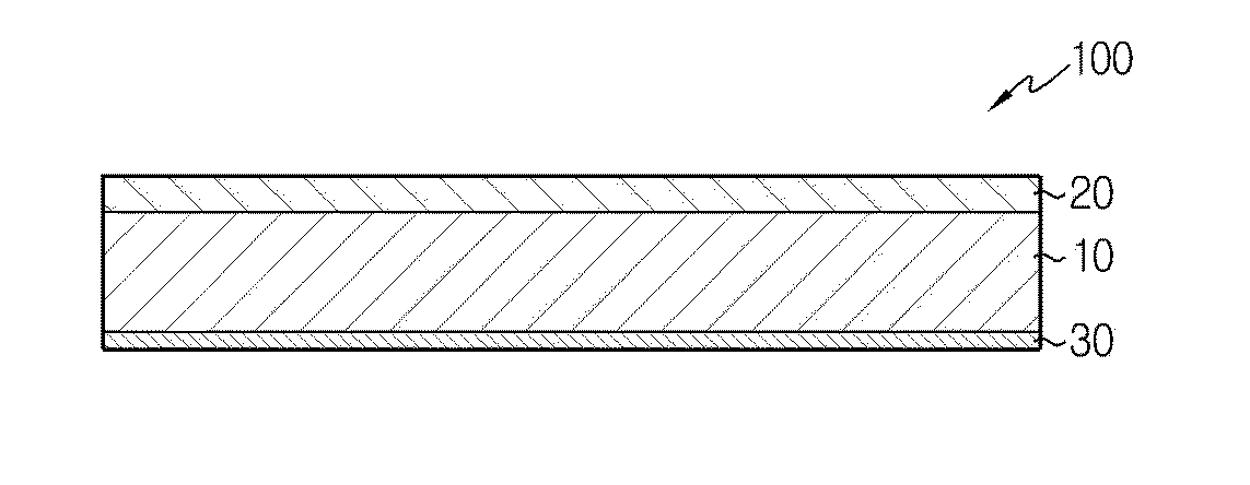
Manufacture of Separator Having Porous Organic-Inorganic Coating Layer and Binder Thin Film Using Non-Solvent by way of Multi-Coating Method

[0059]The procedures of Example 1 were repeated except that on one surface of the porous substrate, the slurry was coated as a lower layer and then the first polymer solution was coated as an upper layer by way of a slide-slot coating method, to prepare a separator.

[0060]The first porous coating layer, in which an additional polymer thin film was further formed, was confirmed to have a thickness of 7.5 μm, and the second porous coating layer obtained from the second polymer solution using the non-solvent was confirmed to have a thickness of 0.9 μm. The separator prepared thus had a superior Gurley number of 780 sec / 100 cc.

experimental example 1

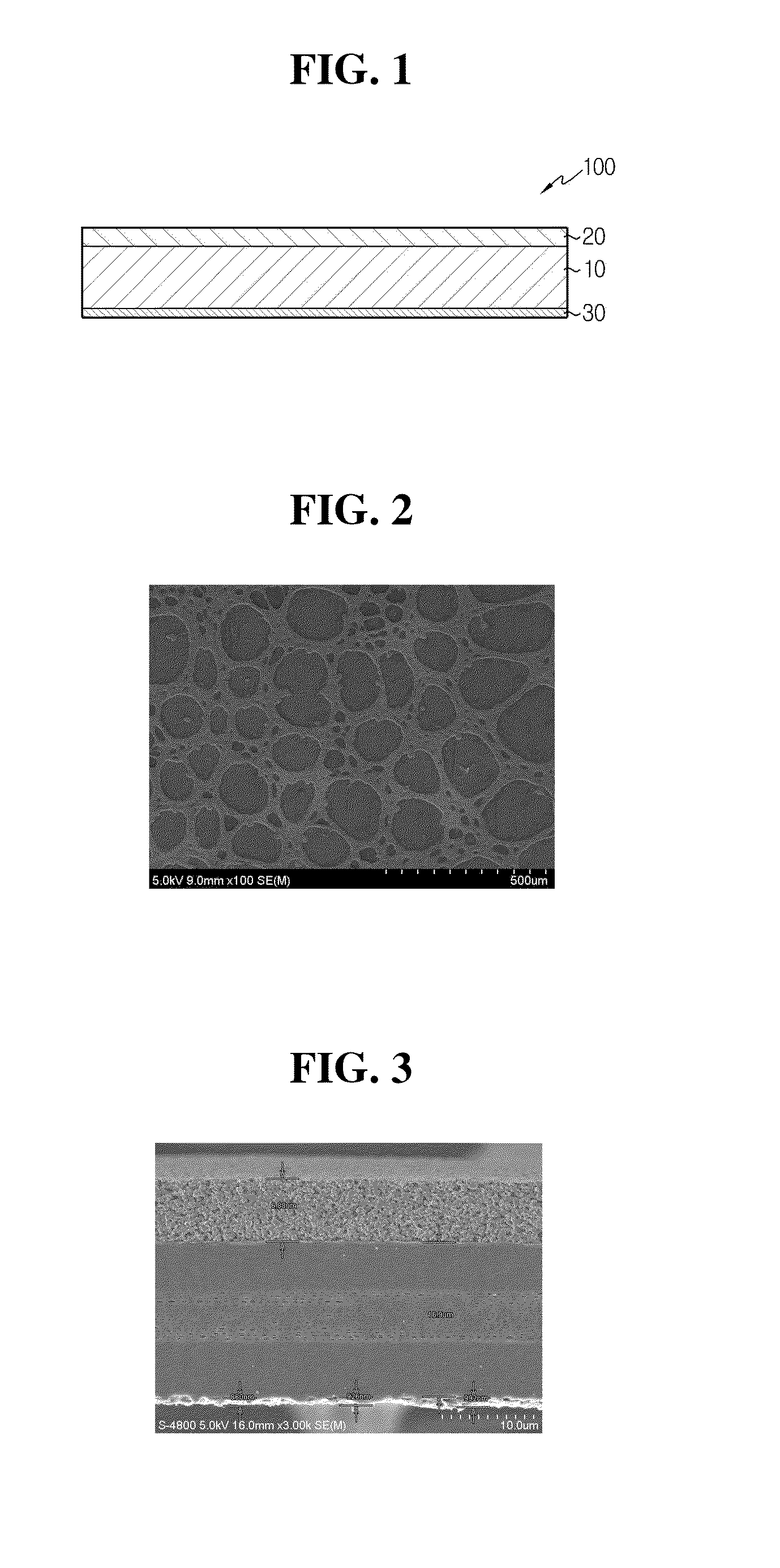
Observation of Separator Surface

[0062]The SEM photographs for the surface and the cross-section of the separator prepared in Example 1 are shown in FIGS. 2 and 3, respectively.

[0063]FIG. 3 is an SEM photograph of the cross-section of a separator according to a preferred embodiment of the present invention.

experimental example 2

Measurement of Battery Output

[0064]Each separator prepared in Example 1 and Comparative Example 1 was interposed between a cathode and an anode, in which the first porous coating layer was in contact with the surface of the cathode and the second porous coating layer was in contact with the anode, to prepare a stacked bi-cell. The bi-cell was again welded on the second porous coating layer, followed by folding, to prepare an electrode assembly.

[0065]Each electrode assembly was measured for discharging resistance under various states of charge (SOC). The results are shown in Table 1.

TABLE 1SOCEx. 1Com. Ex. 195%57.1 mΩ59.5 mΩ50%58.7 mΩ60.0 mΩ30%63.9 mΩ65.5 mΩ

[0066]As shown in Table 1, the electrode assembly having the separator of Example 1 exhibited a lower discharging resistance than that of Comparative Example 1.


PUM

PropertyMeasurementUnit
dielectric constantaaaaaaaaaa
temperatureaaaaaaaaaa
thicknessaaaaaaaaaa

Abstract

The present invention refers to a separator for an electrochemical device and an electrochemical device having the same. More specifically, the separator of the present invention comprises a porous substrate; a first porous coating layer formed on one surface of the porous substrate and comprising a mixture of inorganic particles and a first binder polymer; and a second porous coating layer formed on the other surface of the porous substrate and comprising a product obtained by drying a mixture of a solvent, a non-solvent and a second binder polymer.
Such separator of the present invention can have good thermal safety due to a porous organic-inorganic coating layer formed on one surface thereof, and superior adhesiveness due to a porous coating layer made of a binder thin film formed by applying and drying a mixture of a binder polymer and a non-solvent on the other surface thereof. Also, the separator can have a decreased thickness to reduce the resistance of electrochemical device and improve the capacity thereof.

Description

CROSS-REFERENCE TO RELATED APPLICATION[0001]The present application is a continuation of International Application No. PCT / KR2012 / 009484 filed on Nov. 9, 2012, which claims priority to Korean Patent Application No. 10-2011-0117862 filed in the Republic of Korea on Nov. 11, 2011 and Korean Patent Application No. 10-2012-0126795 filed in the Republic of Korea on Nov. 9, 2012, the disclosures of which are incorporated herein by reference.TECHNICAL FIELD[0002]The present invention relates to a separator for an electrochemical device such as a lithium secondary battery, and an electrochemical device having the same. More particularly, the present invention relates to a separator having a first porous coating layer comprising an organic-inorganic mixture and a second porous coating layer which is a binder layer using a non-solvent, and an electrochemical device having the same.BACKGROUND ART[0003]Recently, there has been an increasing interest in energy storage technology. Electrochemical...

Claims


Application Information

Patent Timeline
Patent Type & Authority Applications(United States)
IPC IPC(8): H01M2/16H01M50/403H01M50/417H01M50/451
CPCH01M2/1686H01M10/052H01M50/44H01M50/461H01M50/446H01M50/451H01M50/403H01M50/417Y02E60/10Y02P70/50H01M10/058H01M50/491H01M50/414H01M50/411H01M50/431H01M50/443H01M50/457H01M10/4235H01M10/0525
Inventor LEE, JOO-SUNGJIN, SUN-MIKIM, JONG-HUNHA, JEONG-MINRYU, BO-KYUNGKIM
Owner TORAY BATTERY SEPARATOR FILM
Why Eureka
Try Eureka