Lead-acid battery

Active Publication Date: 2013-10-24
HITACHI CHEM CO LTD
View PDF6 Cites 12 Cited by
  • Summary
  • Abstract
  • Description
  • Claims
  • Application Information

AI Technical Summary

Benefits of technology

The technical effect of this patent is that it improves the ability of a battery to accept charging initially, and reduces its decrease in charging capacity over time.

Problems solved by technology

However, the technique described in the Patent Document 1 involves a problem in a cycle life test for evaluating the automotive lead-acid battery that the charge acceptance is decreased as the cycle proceeds.
Further, the effect could not be confirmed also for the method described in the Patent Document 2 in the cycle life test described above.

Method used


Image

  • Lead-acid battery
  • Lead-acid battery
  • Lead-acid battery

Examples


example 1

Preparation of Negative Plate

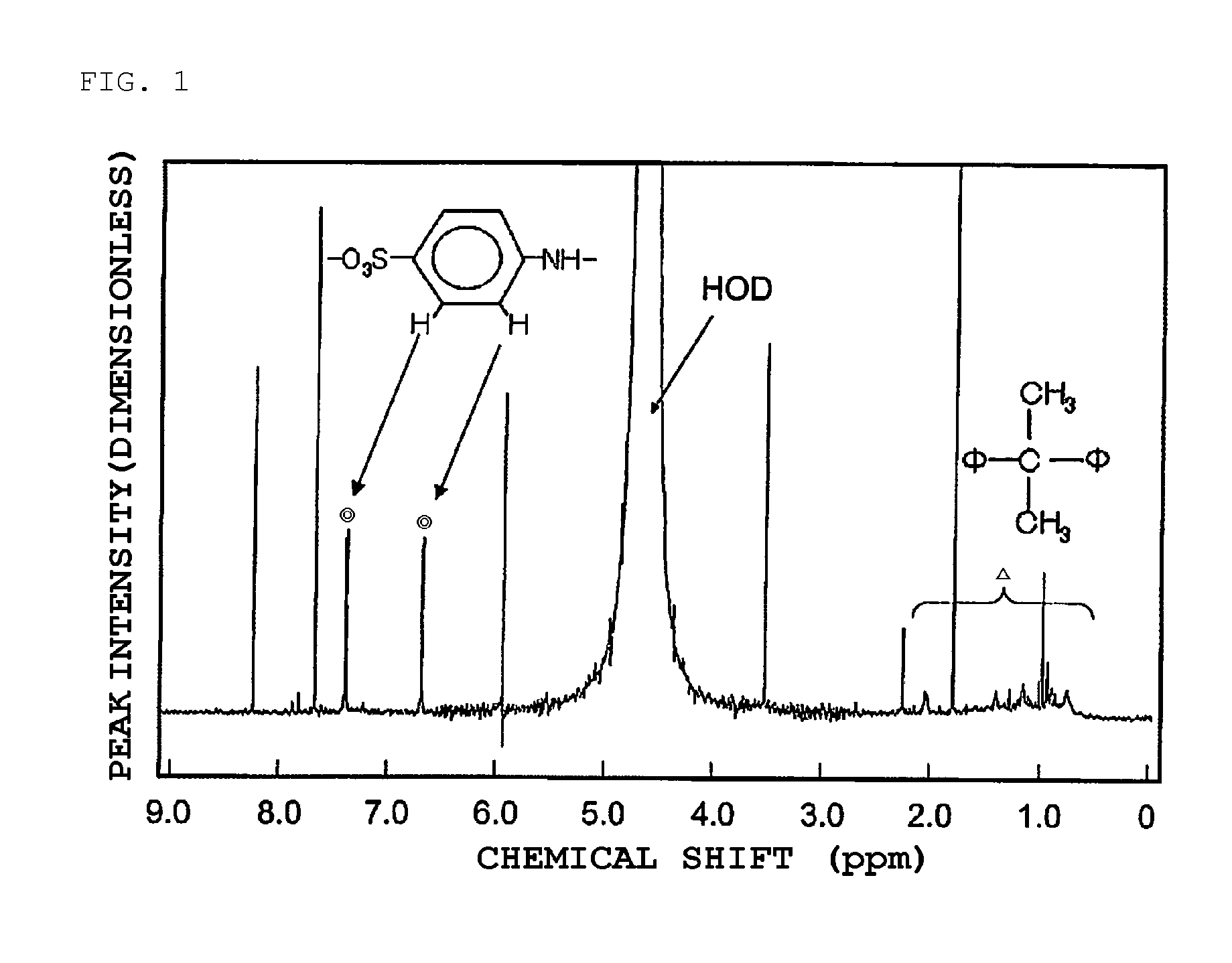
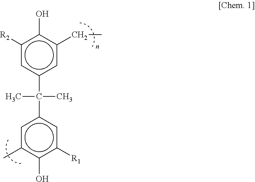
[0031]As a condensate of bisphenols and aminobenzene sulfonic acid, a formaldehyde condensate of bisphenol A and sodium aminobenzene sulfonate represented by the following chemical structural formula [Chem. 1] (molecular weight: 15,000 to 20,000, sulfur content in the compound of 6 to 10 mass %) is used.

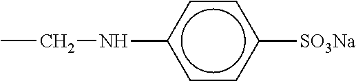
[0032]R1 and R2 represent each hydrogen or

[0033](excluding a case where both R1 and R2 are hydrogen)

[0034]To 100 mass parts of a starting lead powder including lead oxide as a main ingredient, 0.2 mass parts of a formaldehyde condensate of phenol A and sodium aminobenzene sulfonate, 1 mass part of a flake graphite having an average primary particle diameter of 180 μm, 1 mass part of barium sulfate, and 0.1 mass parts of cut fibers (polyester short fibers) were added and mixed and dispersed into the lead powder in a kneader.

[0035]Then, water and a diluted sulfuric acid (specific gravity: 1.26, converted at 20° C.) were dropped and kneaded to prepare a past...

existent examples 1 to 3

[0046]A carbon black prepared from a heavy oil as a starting material (specific surface area: 260 m2 / g) was blended by the following amount instead of the flake graphite in Example 1. That is, to 100 mass parts of the starting lead powder including lead oxide as the main ingredient, the carbon black was blended by 0.3 mass parts in Existent Example 1, 0.5 mass parts in Existent Example 2, and 1 mass part in Existent Example 3, and 75D23 type batteries were manufactured in the same manner as in Example 1 except for the change described above.

examples 8 to 14

[0047]In Example 1, the flake graphite was blended by the following amounts while changing the blending amount thereof. That is, to 100 mass parts of the starting lead powder including lead oxide as a main ingredient, the flake graphite was blended by 0.2 mass parts in Example 8, 0.4 mass parts in Example 9, 0.5 mass parts in Example 10, 1.5 mass parts in example 11, 2 mass parts in Example 12, 2.5 mass parts in Example 13, and 3 mass parts in Example 14, and 75D23 type batteries were manufactured in the same manner as in Example 1 except for the change described above.

[0048]The content of the blended flake graphite in Examples 8 to 14 was 0.2 mass parts, 0.4 mass parts, 0.5 mass parts, 1.6 mass parts, 2.2 mass parts, 2.7 mass parts, and 3.2 mass parts, respectively based on 100 mass parts of the negative active material (spongy metallic lead) in a fully charged state.


PUM


Abstract

A lead-acid battery improving the charge acceptance in an initial stage, suppressing the decrease of the charge acceptance for a long time use of the battery and having a long life is provided. In a lead-acid battery using a paste type negative plate prepared by filling a past form negative active material using a lead powder as a starting material in a collector made of a lead alloy, a flake graphite and a condensate of bisphenols and aminobenzene sulfonic acid are contained in the negative active material. The average primary particle diameter of the flake graphite is 10 μm or more and 220 μm or less, preferably, 100 μm or more and 220 μm or less. The content of the flake graphite is preferably from 0.5 mass parts to 2.7 mass parts and, more preferably, from 1.1 mass parts to 2.2 mass parts based on 100 mass parts of the negative active material (spongy metallic lead) in a fully charged state.

Description

TECHNICAL FIELD[0001]The present invention relates to a lead-acid battery.BACKGROUND ART[0002]Automotive lead-acid batteries have been used generally for starting engines and supplying power to electric components. In recent years, for environmental preservation and fuel cost improvement, idling stop and start of stopping an engine during temporary stopping of a vehicle and re-starting the engine upon starting (hereinafter referred to as ISS) has been introduced. Since engine starting and stopping are repeated frequently in ISS, the number of high rate discharge cycles increases in batteries upon starring the engine, and discharge load is increased being coupled with the use of electric components. A Battery has been charged by constant voltage charging as usual by an alternator, and a setting value for the alternator voltage has been lowered in recent years with an aim of reducing the decrease of electrolyte due to electrolyzing water during charging. In addition to the low charge ...

Claims


Application Information

Patent Timeline
IPC IPC(8): H01M10/06H01M50/417H01M50/437
CPCH01M10/06H01M4/0416H01M4/20H01M4/56H01M4/685H01M4/62H01M4/628H01M10/14H01M10/4235H01M2004/021Y02E60/10H01M50/44Y02P70/50H01M50/437H01M50/417H01M4/14H01M4/583H01M10/12H01M4/606H01M50/409H01M50/491Y02T10/70
Inventor KOGURE, KOJITODUKA, MASATOSHI
Owner HITACHI CHEM CO LTD
Why Eureka
Try Eureka