

Adsorbed Natural Gas Storage Facility
a natural gas storage facility and gas storage technology, applied in the direction of gas/liquid distribution and storage, gaseous fuels, lighting and heating apparatus, etc., can solve the problems of large natural gas transportation network problems, diurnal demand, and people, unlike manufacturing plants or facilities, tend to be unrelenting energy users, etc., to reduce system pressure variations, reduce the pressure of natural gas sources, and prolong the operation life of rotational equipmen
- Summary
- Abstract
- Description
- Claims
- Application Information
AI Technical Summary
Benefits of technology
Problems solved by technology
Method used
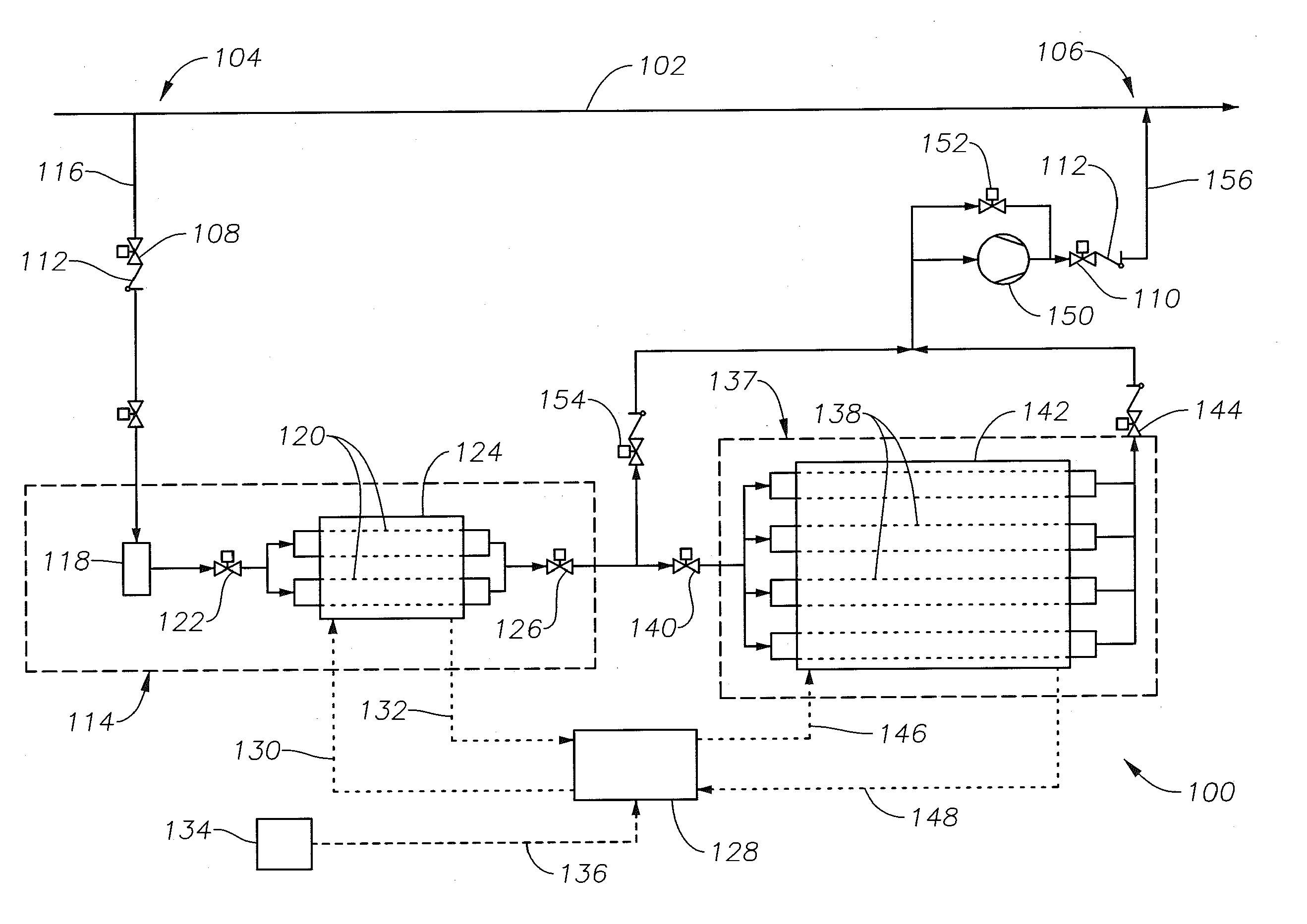
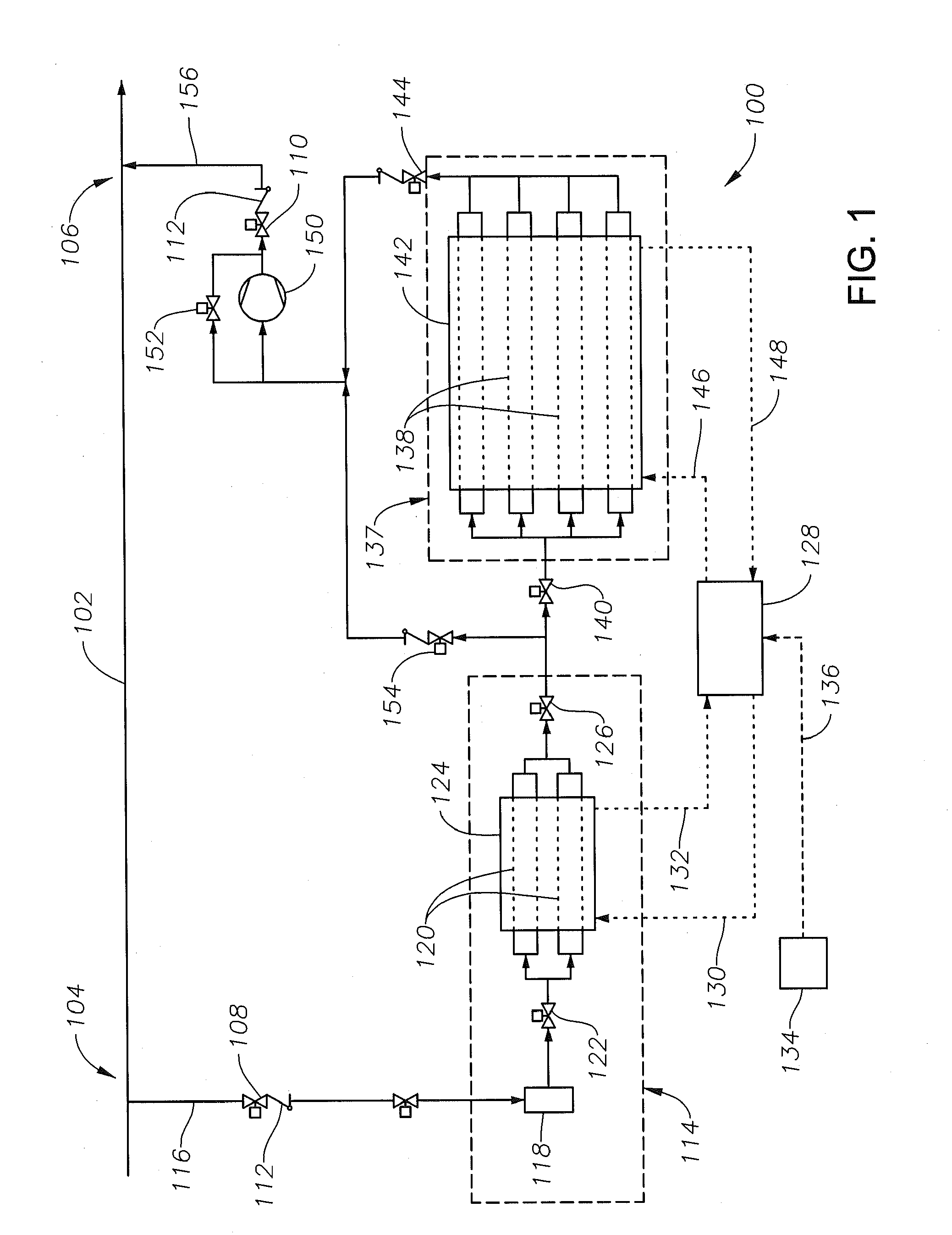
Image

Examples
Embodiment Construction
[0029]The Specification, which includes the Summary of Invention, Brief Description of the Drawings and the Detailed Description of the Preferred Embodiments, and the appended Claims refer to particular features (including process or method steps) of the invention. Those of skill in the art understand that the invention includes all possible combinations and uses of particular features described in the Specification. Those of skill in the art understand that the invention is not limited to or by the description of embodiments given in the Specification. The inventive subject matter is not restricted except only in the spirit of the Specification and appended Claims.
[0030]Those of skill in the art also understand that the terminology used for describing particular embodiments does not limit the scope or breadth of the invention. In interpreting the Specification and appended Claims, all terms should be interpreted in the broadest possible manner consistent with the context of each te...
PUM
| Property | Measurement | Unit |
|---|---|---|
| Pore Width | aaaaa | aaaaa |
| density | aaaaa | aaaaa |
| pressure | aaaaa | aaaaa |
Abstract
Description
Claims
Application Information