Liquid Metal Digital Manufacturing System

a digital manufacturing system and metal technology, applied in the field of layered manufacturing, can solve the problems of metal system cost decline, metal oxide contamination, and low cost of polymer systems, and achieve the effect of enhancing the shape accuracy and reducing oxide and other contamination

Inactive Publication Date: 2013-10-31
RAMSUNDAR PALLANT SATNARINE
View PDF7 Cites 30 Cited by
  • Summary
  • Abstract
  • Description
  • Claims
  • Application Information

AI Technical Summary

Benefits of technology

[0043]In another aspect of the invention there is provided means to maintain an inert atmosphere during deposition to reduce oxide and other contamination.
[0044]In another aspect of the i

Problems solved by technology

While we have seen a dramatic decline in the cost of polymer AM systems over the years, the AM systems available for metals are still relatively expensive.
Some other limitations on available AM systems for metals are low production rates compared

Method used


Image

  • Liquid Metal Digital Manufacturing System
  • Liquid Metal Digital Manufacturing System
  • Liquid Metal Digital Manufacturing System

Examples


Embodiment Construction

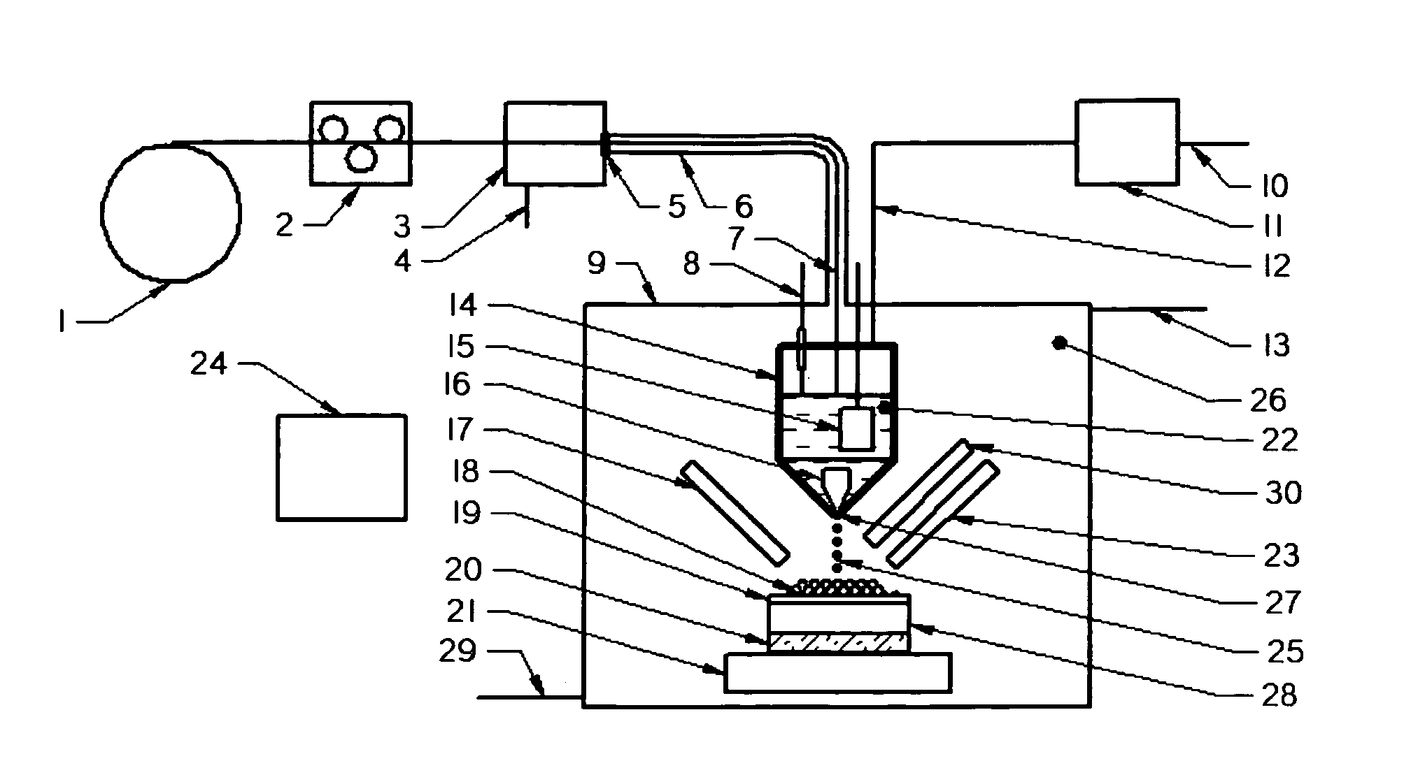
[0048]Referring to FIG. 1, the Metal Deposition Head 44 and the Support Material Deposition Head 45 are mounted on a computer numerical control beam 46. The deposits are made on the substrate 19 which rests on the heated block 28. The heated block 28 is insulated from the computer numerical control table 21 by the insulated pad 20. The working area of the apparatus is kept in an inert atmosphere contained in the enclosure 9.

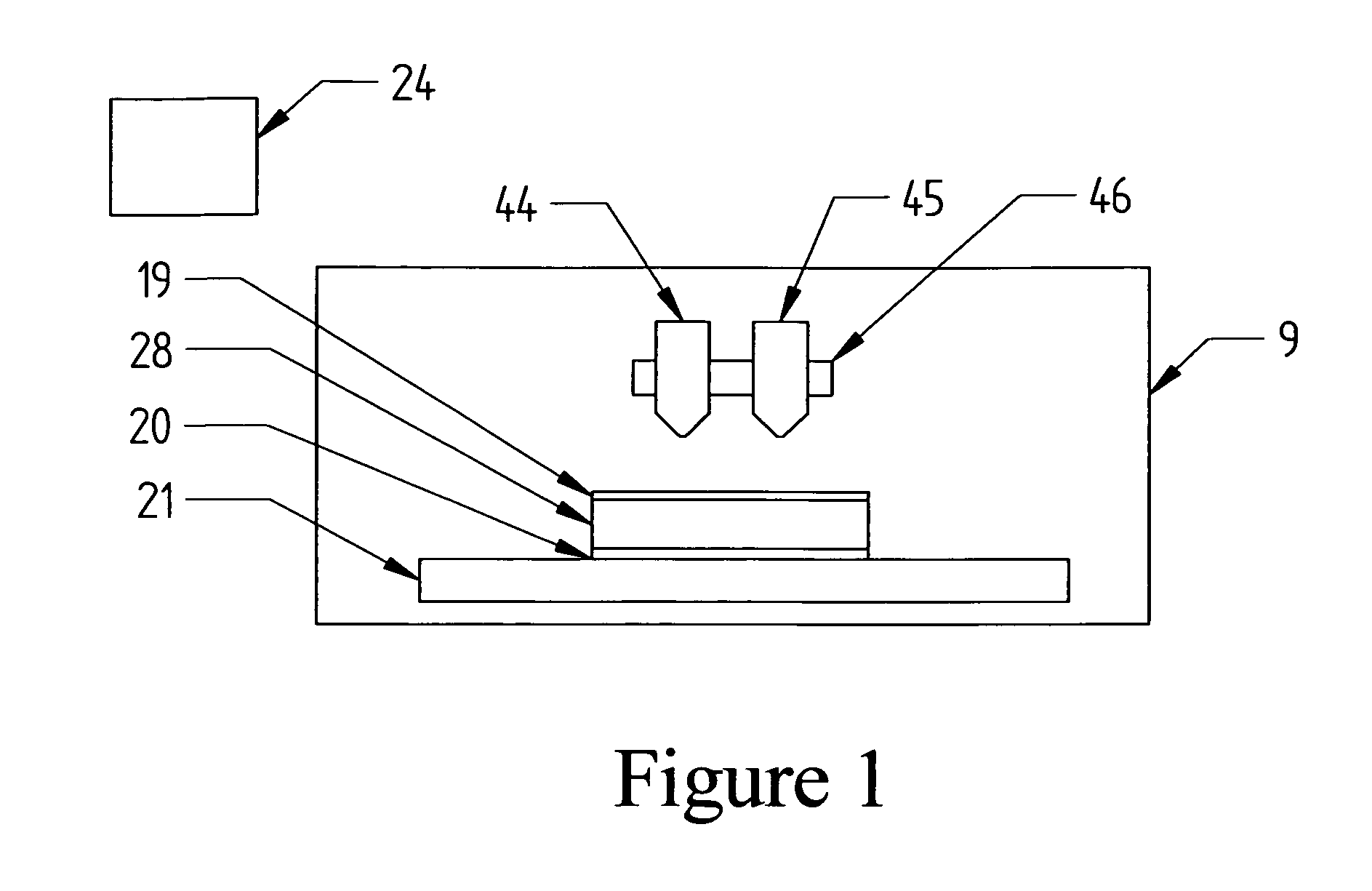
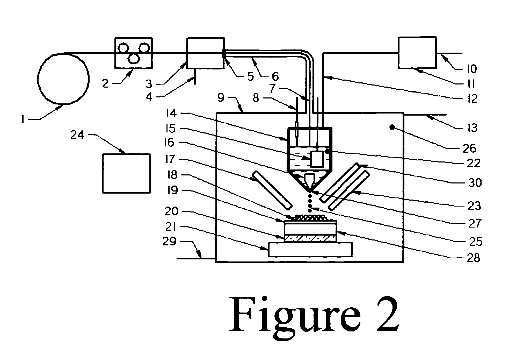
[0049]FIG. 2 shows details of the metal deposition head 44. The raw material, supplied as a coil of wire 1 is fed by the wire feeder 2 into a descalar 3 which removes the oxide coating on the wire. The oxide coating removed is disposed through the exhaust port 4 and the clean wire 7 passes through the seal 5 into a passage 6 filled with an inert gas 26. The clean wire 7 terminates into the melt chamber 14. The melt chamber 14 is an air-tight chamber containing the following:[0050]a) Heating elements 15 which acts to liquefy the wire and create a melt pool 22.[005...


PUM

PropertyMeasurementUnit
Temperatureaaaaaaaaaa
Shapeaaaaaaaaaa
Melting pointaaaaaaaaaa

Abstract

A process and apparatus for the production of metal parts by layered manufacturing starting from wire raw material comprising of the steps of; descaling of the wire; creating and maintaining a melt pool of the metal in a melt chamber; expelling controlled amounts of melt from the melt chamber in predetermined layer patterns, which solidify to form a desired object; managing the solidification parameters to achieve the deposit cross sections desired and depositing a removable support material to assist in maintaining the geometry of the desired metal deposit. Said apparatus is capable of higher production rate than other metal layered manufacturing systems available commercially and can be used for any metal alloy or non-metal material that can be supplied in wire form and that is within the melt capacity of this invention.

Description

CROSS-REFERENCE TO RELATED APPLICATIONS[0001]The present application claims the benefit of the filing date of U.S. Provisional Patent Application No. 61 / 640,712 filed Apr. 30, 2012, the contents of which are hereby expressly incorporated by reference.STATEMENT REGARDING FEDERALLY SPONSORED RESEARCH OR DEVELOPMENT[0002]Not ApplicableREFERENCE TO SEQUENCE LISTING, A TABLE, OR A COMPUTER PROGRAM LISTING COMPACT DISK APPENDIX[0003]Not ApplicableFIELD OF THE INVENTION[0004]This invention is in the field of layered manufacturing. Layered manufacturing is the construction of a three dimensional object by building a series of thin successive layers one on top of the other.[0005]More particularly, this invention is a method and apparatus for the layered production of metal articles by liquefying the metal and then controlling the deposition and solidification of the layers to produce the required part.BACKGROUND OF THE INVENTION[0006]The field of additive manufacturing (AM) has shown explosi...

Claims


Application Information

Patent Timeline
IPC IPC(8): B05D1/38
CPCB05D1/38B22F2999/00B29C64/112B33Y10/00B33Y30/00Y02P10/25B22F12/53B22F10/32B22F10/25B22F10/22B22F12/90B22F9/08
Inventor RAMSUNDAR, PALLANT SATNARINE
Owner RAMSUNDAR PALLANT SATNARINE
Why Eureka
Try Eureka