
Deposition of an amorphous carbon layer with high film density and high etch selectivity

Active Publication Date: 2013-11-14
APPLIED MATERIALS INC
View PDF0 Cites 26 Cited by
  • Summary
  • Abstract
  • Description
  • Claims
  • Application Information

AI Technical Summary

Benefits of technology

The present invention provides a method for creating a hard mask with high film density, etch selectivity, and ashability, while maintaining good line integrity for small devices. This helps to create a thinner hard mask that improves etch margin and allows for controlled etching of smaller features without causing issues like line wiggling and bending.

Problems solved by technology

The etch selectivity can be increased by, for example, densifying the amorphous carbon film, which, however, results in high compressive film stress that may significantly impact the feature transfer during the lithographic process.

Method used


Image

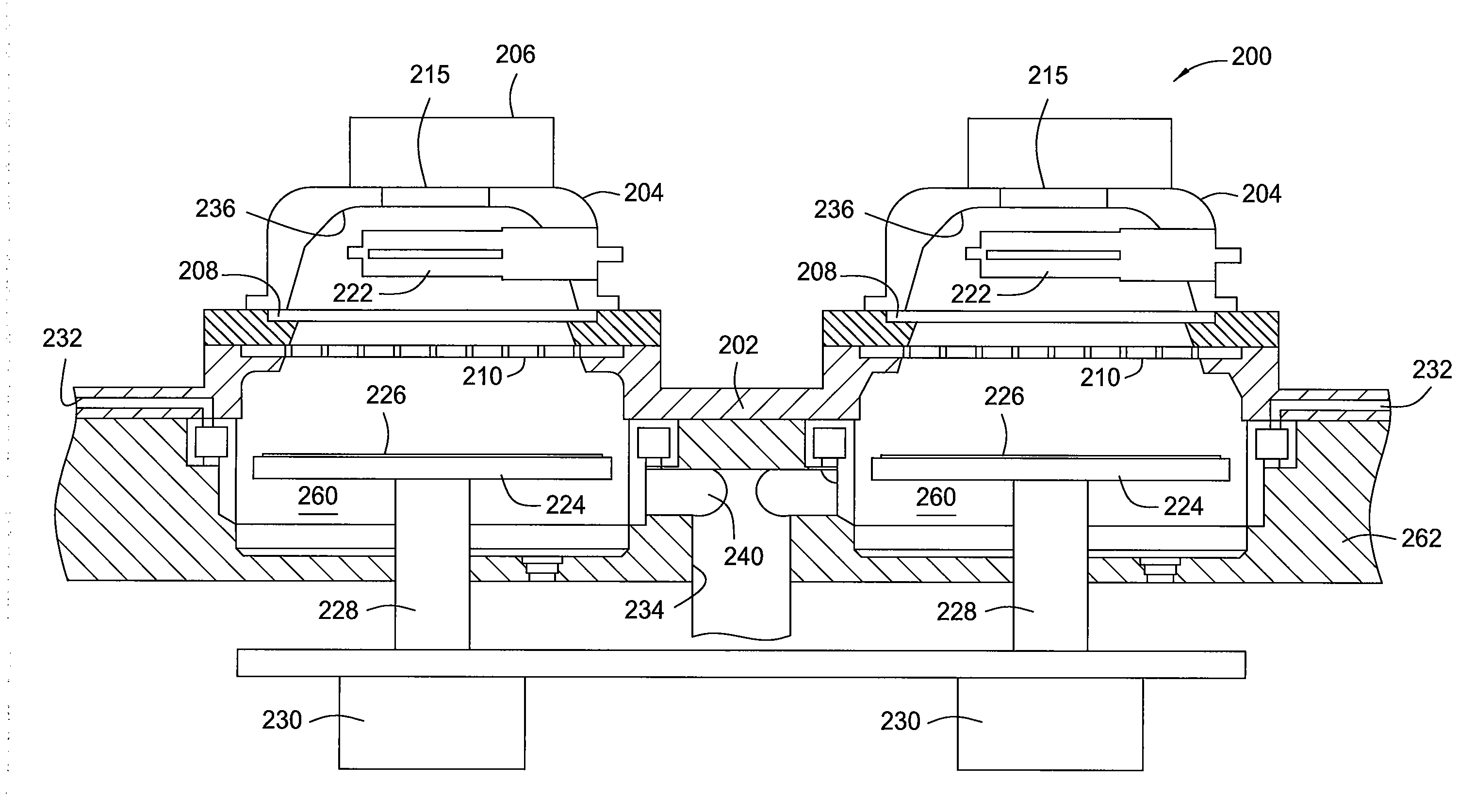
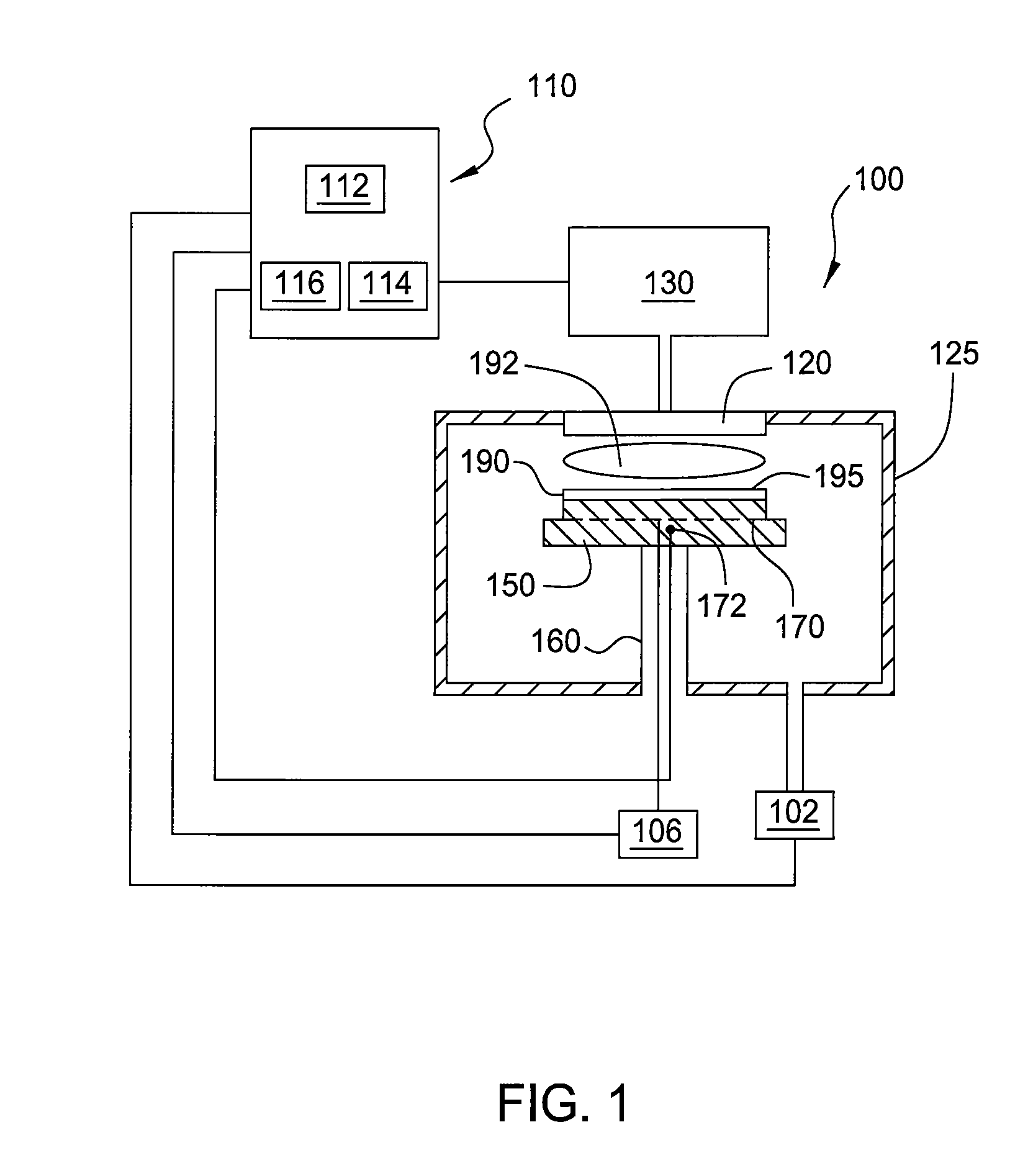
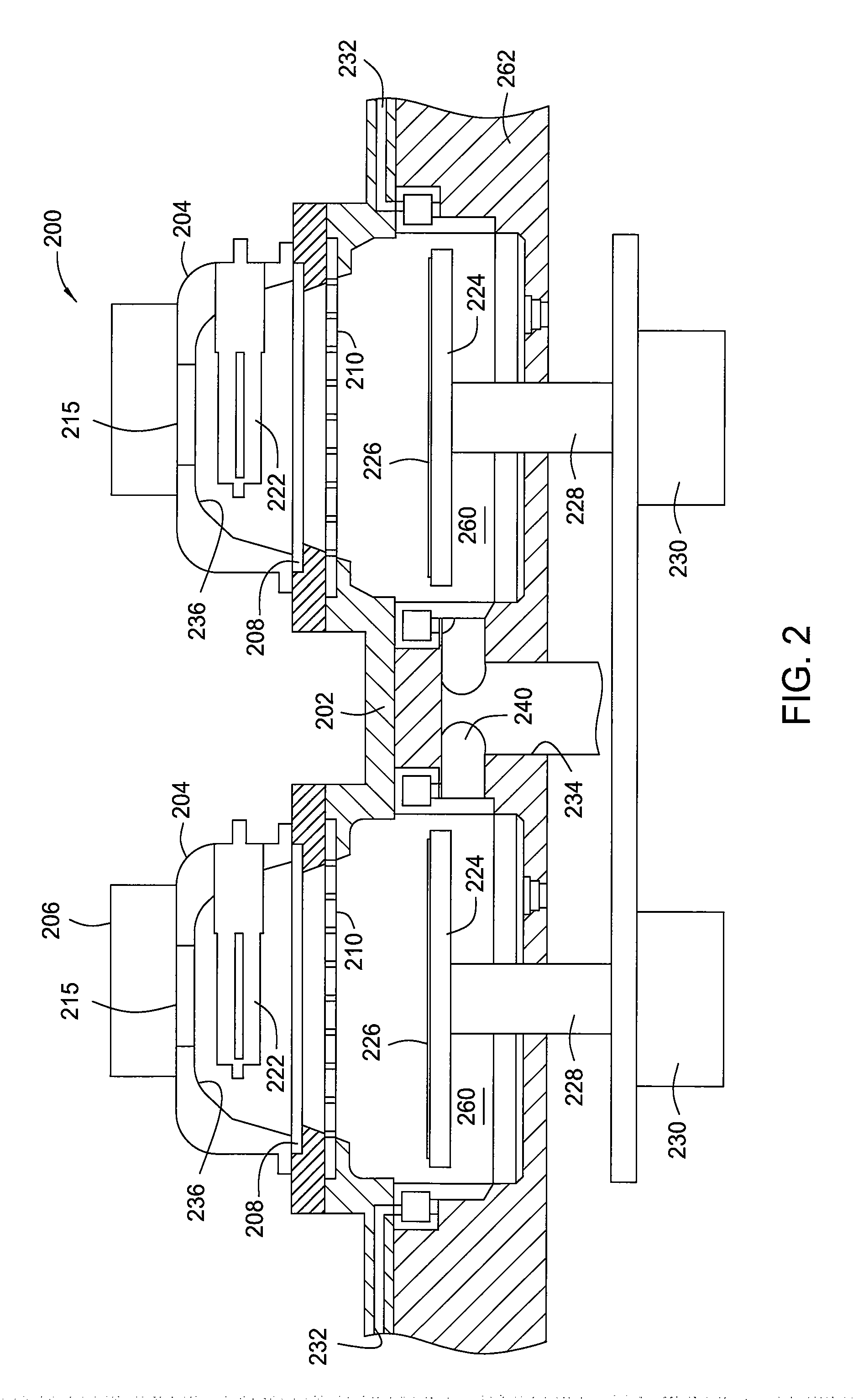
  • Deposition of an amorphous carbon layer with high film density and high etch selectivity
  • Deposition of an amorphous carbon layer with high film density and high etch selectivity
  • Deposition of an amorphous carbon layer with high film density and high etch selectivity

Examples


example

[0053]The following non-limiting example is provided to further illustrate embodiments described herein regarding UV curing of amorphous carbon layer. However, the examples are not intended to be all inclusive and are not intended to limit the scope of the embodiments described herein.

[0054]A substrate having an amorphous carbon layer deposited in a manner as described in step 402 is exposed to UV radiation at a chamber temperature of about 550° C. and applied power of about 1,350 milliWatts / cm2 at a wavelength of about 400 nm for about 900 seconds. The UV curing may be conducted in an Argon and Helium atmosphere with an Ar flow of about 16,000 sccm, He flow of about 16000 sccm and pressure of 6 torr. After UV curing, the amorphous carbon layer exhibits —H content less than about 20% and an increased film density up to 1.98 g / cc.

[0055]FIG. 5 depicts scanning electron microscope images illustrating a comparison of the patterning performance comparison for an amorphous carbon layer “A...


PUM

PropertyMeasurementUnit
Temperatureaaaaaaaaaa

Abstract

Embodiments described herein relate to a method for processing a substrate. In one embodiment, the method includes introducing a gas mixture comprising a hydrocarbon source and a diluent gas into a deposition chamber located within a processing system, generating a plasma from the gas mixture in the deposition chamber at a temperature between about 200° C. and about 700° C. to form a low-hydrogen content amorphous carbon layer on the substrate, transferring the substrate into a curing chamber located within the processing system without breaking vacuum, and exposing the substrate to UV radiation within the curing chamber at a curing temperature above about 200° C.

Description

BACKGROUND OF THE INVENTION[0001]1. Field[0002]Embodiments of the present invention generally relate to the fabrication of integrated circuits and particularly to the deposition of an amorphous carbon layer with high film density and high etch selectivity.[0003]2. Description of the Related Art[0004]Carbon-based materials, such as amorphous carbon (denoted as a-C), has been proved to be an effective material serving as etch hardmask for oxide, nitride, poly-Si, or metal (e.g., Al) materials due to its chemical inertness, optical transparency, and good mechanical properties.[0005]To ensure that the desired amorphous carbon film adequately protects underlying material layer during the subsequent etching process, it is important that amorphous carbon film possesses a relatively high etch selectivity, or removal rate ratio, with respect to material layer thereunder. Higher etch selectivity is required to transfer the patterns to underlayers accurately. The etch selectivity can be increa...

Claims


Application Information

Patent Timeline
IPC IPC(8): H01L21/02
CPCH01L21/02527H01L21/02592H01L21/0262H01L21/02115H01L21/02274H01L21/02348H01L21/31144C23C16/26C23C16/56H01L21/3065C23C16/48C23C16/52
Inventor REILLY, PATRICKSHAIKH, SHAHIDSUMMAN, TERSEMPADHI, DEENESHBALUJA, SANJEEVROCHA-ALVAREZ, JUAN CARLOSNOWAK, THOMASKIM, BOK HOENWITTY, DEREK R.
Owner APPLIED MATERIALS INC
Learn More