
Small Spot Size Spectroscopic Ellipsometer

a spectroscopic ellipsometer and small spot technology, applied in the field of optical metrology systems and methods, can solve the problems of reduced measurement sensitivity, difficult characterization, and increased difficulty in characterization, and achieve the effects of improving measurement sensitivity, high angular resolution, and large numerical apertur

Active Publication Date: 2013-12-05
KLA CORP
View PDF19 Cites 64 Cited by
  • Summary
  • Abstract
  • Description
  • Claims
  • Application Information

AI Technical Summary

Benefits of technology

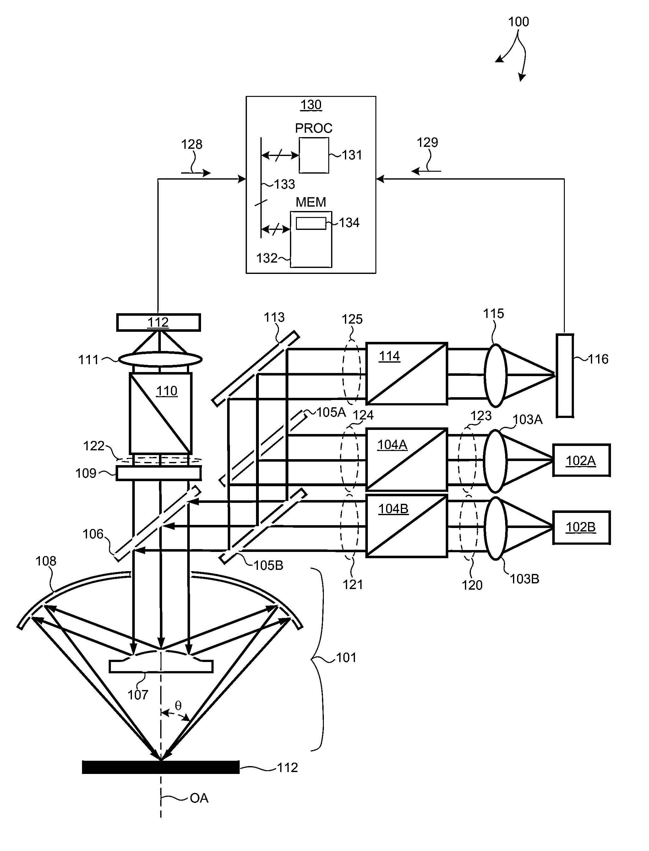
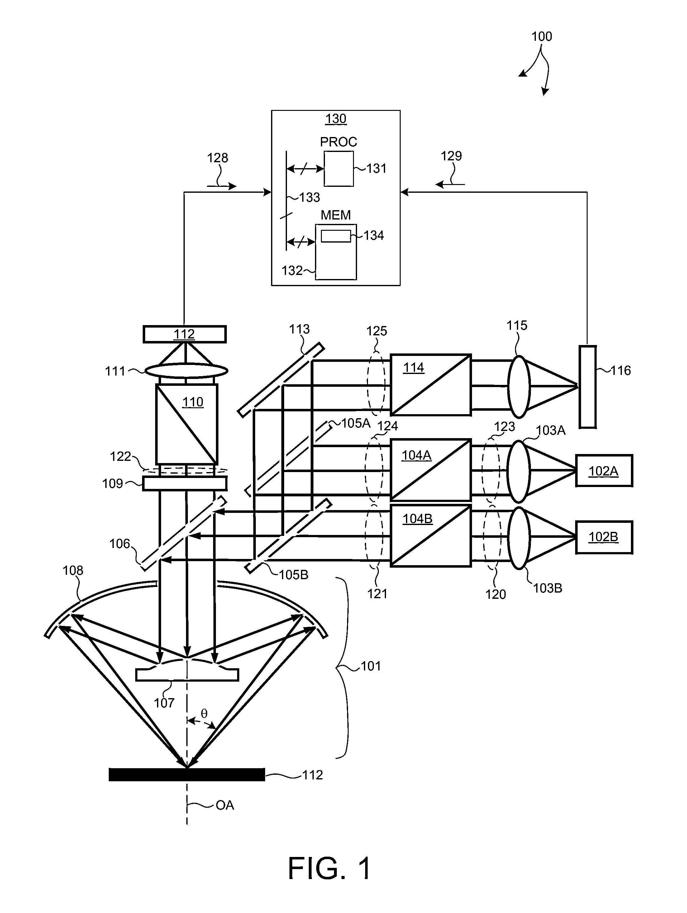
The invention is a small angle CD metrology system that combines a small angle spectroscopic ellipsometry (SE) subsystem and a small angle spectroscopic reflectometry system. The SE subsystem operates in a complete Kupper Matrix mode to improve measurement sensitivity. The system also includes an all-reflective objective with high numerical aperture and reduced measurement spot size. The system measures at two orthogonal or nearly orthogonal azimuth angles to further improve sensitivity. Additionally, the system includes a dynamic aperture subsystem that allows for measurements at different angles of incidence and azimuth angles to improve sensitivity.

Problems solved by technology

As devices (e.g., logic and memory devices) move toward smaller nanometer-scale dimensions, characterization becomes more difficult.
Devices incorporating complex three-dimensional geometry and materials with diverse physical properties contribute to characterization difficulty.
For measurements of optically isotropic materials with typical RPSE and RCSE systems, selection of small angles of incidence results in substantially reduced measurement sensitivity.
As critical dimensions (e.g., the gate width or gate oxide thickness) continue to decrease, maintaining measurement precision (e.g., “3-sigma” measurement values) and tool-to-tool matching becomes progressively more difficult.
As a result, both precision and tool-to-tool matching degrade.
Measurement precision and tool-to-tool matching are core challenges in the development of an optical metrology system that meets customer requirements of the semiconductor industry.

Method used


Image

  • Small Spot Size Spectroscopic Ellipsometer
  • Small Spot Size Spectroscopic Ellipsometer
  • Small Spot Size Spectroscopic Ellipsometer

Examples


Embodiment Construction

[0023]Reference will now be made in detail to background examples and some embodiments of the invention, examples of which are illustrated in the accompanying drawings.

[0024]Methods and systems for Critical Dimension (CD) measurement applications with high sensitivity and throughput requirements are presented. Such systems are employed to measure structural and material characteristics (e.g., material composition, dimensional characteristics of structures and films, etc.) associated with different semiconductor fabrication processes.

[0025]A small angle CD metrology system with a small spot size is introduced to increase measurement sensitivity while maintaining adequate throughput necessary for modern semiconductor manufacture. As the size of CD measurement targets continue to shrink, the desired spot size also becomes smaller. The system introduced herein is able to measure CD measurement targets with high sensitivity over a small spot size (e.g., a spot size of 15 microns in diame...


PUM

PropertyMeasurementUnit
collection angleaaaaaaaaaa
angle of incidenceaaaaaaaaaa
diameteraaaaaaaaaa

Abstract

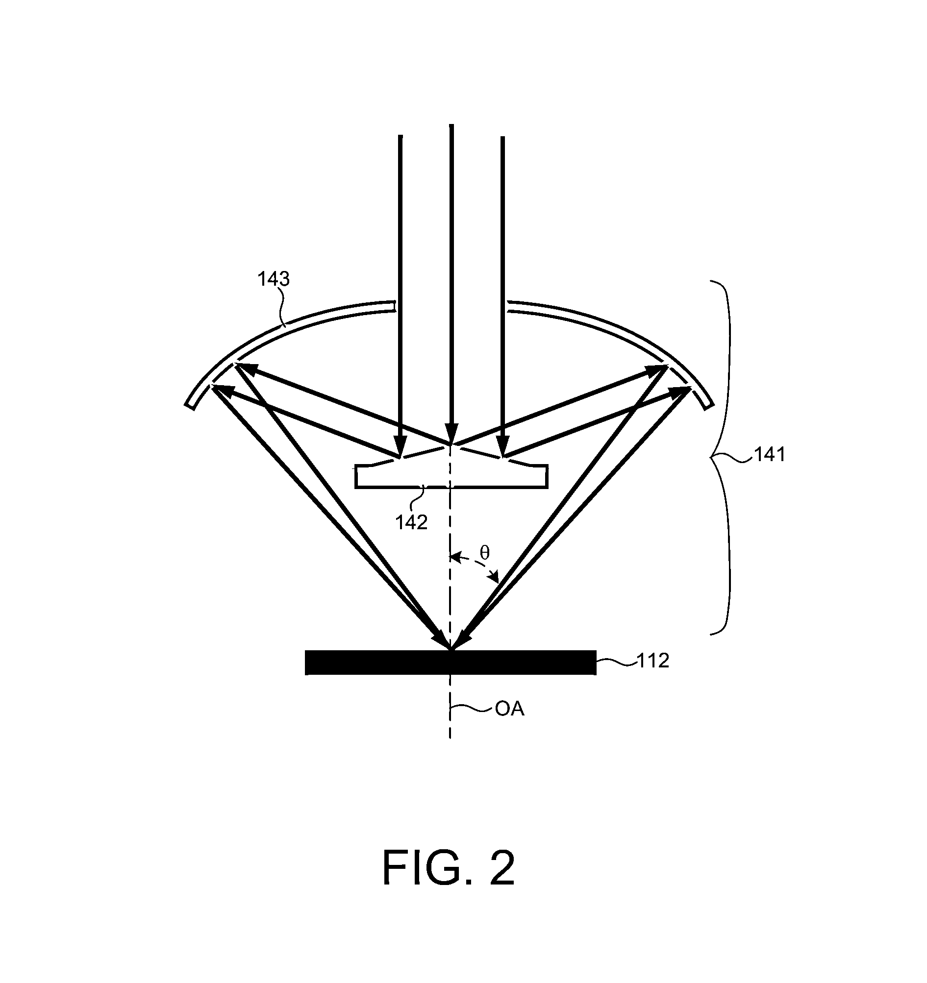
Methods and systems for small angle CD metrology with a small spot size are introduced to increase measurement sensitivity while maintaining adequate throughput necessary for modern semiconductor manufacture. A small angle CD metrology system includes a small angle spectroscopic ellipsometry (SE) subsystem combined with a small angle spectroscopic reflectometry system, both operated at small angles of incidence. The small angle SE subsystem is configured to operate in a complete Mueller Matrix mode to further improve measurement sensitivity. The small angle CD metrology system includes an objective having all reflective surfaces in the light path. In some embodiments, the all-reflective objective is a Schwartzschild objective having an axicon mirror element to further reduce measurement spot size. In some embodiments, the small angle CD metrology system includes a dynamic aperture subsystem to isolate specific ranges of angles of incidence and azimuth for improved measurement sensitivity.

Description

CROSS REFERENCE TO RELATED APPLICATION[0001]The present application for patent claims priority under 35 U.S.C. §119 from U.S. provisional patent application Ser. No. 61 / 652,769, entitled “Small Spot Size, High Sensitivity, High Speed Mueller Matrix Spectroscopic Ellipsometric System and Method,” filed May 29, 2012, the subject matter of which is incorporated herein by reference in its entirety.TECHNICAL FIELD[0002]The described embodiments relate to optical metrology systems and methods, and more particularly to methods and systems for improved precision across critical dimension measurement applications.BACKGROUND INFORMATION[0003]Semiconductor devices such as logic and memory devices are typically fabricated by a sequence of processing steps applied to a specimen. The various features and multiple structural levels of the semiconductor devices are formed by these processing steps. For example, lithography among others is one semiconductor fabrication process that involves generati...

Claims


Application Information

Patent Timeline
Patent Type & Authority Applications(United States)
IPC IPC(8): G01N21/21
CPCG01N21/211G03F7/70625
Inventor WANG, HAIMINGKRISHNAN, SHANKAR
Owner KLA CORP
Learn More