Reaction apparatus and method using supercritical water or subcritical water

a technology of supercritical water and water, applied in the direction of glucose production, organic chemistry, bulk chemical production, etc., can solve the problems of difficult to precisely control the pressure, high energy consumption for raising the temperature and pressure of water, and low concentration of glycerin in the raw material, so as to reduce the amount of tar produced, the effect of high raw material concentration and different density

Inactive Publication Date: 2013-12-19
KONDO TAKEYUKI +5
View PDF0 Cites 9 Cited by
  • Summary
  • Abstract
  • Description
  • Claims
  • Application Information

AI Technical Summary

Benefits of technology

[0018]According to this invention, since the raw material fluid containing at least one member of glycerin, cellulose, and lignin and the supercritical water or subcritical water are agitated rapidly and sufficiently by the agitation blade set within the mixing flow path, mixing properties between the raw material fluid and the supercritical water or subcritical water, both of which are largely different in the density from each other due to the high concentration of the raw material, can be enhanced. As a result, it becomes possible to decrease the amount of tar produced as a reaction by-product and to increase a fluid shear force on the wall surface of the mixing flow path. Thus, it is possible to exfoliate and remove carbon produced due to carbonization of the tar deposited onto the reaction pipe wall surface. Furthermore, the agitation blade is rotated by kinetic energy of the mixed fluid, so that an external rotation drive device is not necessary. Thus, the structure can be simplified.
[0019]In addition, since the reaction solution originating from the reaction in the first mixing pipe and the cooling water can be mixed rapidly and sufficiently by the agitation blade set within the second mixing pipe, mixing properties between the raw material fluid and the supercritical water or subcritical water, both of which are largely different in the density from each other due to the high concentration of the raw material, can be enhanced, and it is possible to decrease the amount of tar produced as a reaction by-product. In addition, a fluid shear force on the wall surface of the mixing flow path can be increased, and hence, it is possible to exfoliate and remove carbon produced due to carbonization of the tar deposited onto the reaction pipe wall surface. In addition, the agitation blade is rotated by kinetic energy of the mixed fluid, so that an external rotation drive device is not necessary. Thus, the structure can be simplified.

Problems solved by technology

However, according to the method of Masaharu Watanabe, et al., “Acrolein synthesis from glycerol in hot-compressed water”, the concentration of glycerin in the raw material is low as about 1%, and much energy is consumed for raising the temperature and pressure of water.
Thus, there may be a possibility that it is difficult to precisely control the pressure.
In addition, when the tar produced deposits onto the reaction pipe wall surface, the wall surface is carbonized, and therefore, blockage of the pipe is liable to occur.
In general, while water in a state at ordinary temperature and normal pressure has large dielectric constant and high solubility of salts, water in a supercritical state is liable to cause deposition of salts due to a decrease of the dielectric constant.
However, there is involved such a problem that since the inner wall of a reaction pipe is porous, when the salt once deposits, it enters the inside of the pore and cannot be removed.
Thus, there is involved such a problem that much energy is required at the time of pushing the scraper.
However, there is involved such a problem that the solid deposited onto the inner surface of an inner pipe of the double-pipe heat exchanger or on the wall surface of the reaction pipe which will become high in the temperature cannot be removed.

Method used


Image

  • Reaction apparatus and method using supercritical water or subcritical water
  • Reaction apparatus and method using supercritical water or subcritical water
  • Reaction apparatus and method using supercritical water or subcritical water

Examples


example 1

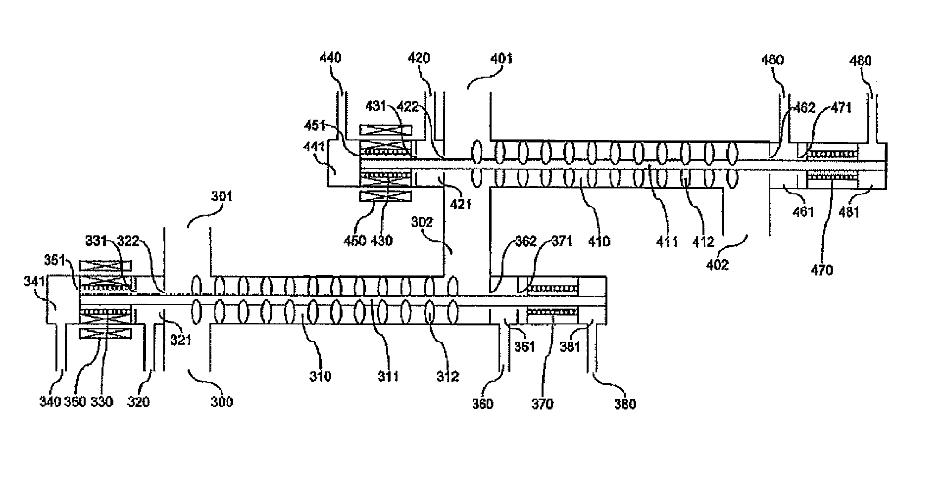
[0034]FIG. 6 shows a mixing pipe according to Example 1 of this invention and shows an example of a structure of a mixing flow path with a built-in agitator. A raw material fluid containing glycerin and sulfuric acid and a supercritical water are sent from an inlet flow path (300) and an inlet flow patch (301), respectively to a mixing pipe (310). An agitation blade (312) is connected to an agitation shaft (311) set within the mixing pipe (310) and rotated while allowing a center shaft of the mixing flow path to act as a rotating shaft by means of an upstream-side bearing (330) and a downstream-side bearing (370) of the mixing flow path, thereby performing mixing of the fluid.

[0035]The agitation blade is rotated by the kinetic energy of the fluid flowing through the mixing flow path. A diameter of the mixing flow path is from 1 to 10 cm, and a flow rate is desirably from 2 to 10 m / sec. This is because when the flow rate is less than 2 m / sec, the mixing performance is lowered, wherea...

example 2

[0040]FIG. 9 shows a mixing pipe according to Example 2 of this invention and shows other example of a structure of a mixing flow path with a built-in agitator. In Example 2, the agitation blade is rotated by an external rotation drive system set outside the mixing pipe.

[0041]An upstream-side bearing (330) and a downstream-side bearing (370) of the mixing pipe are cooled by cooling waters flown from an upstream-side cooling water inlet (340) and a downstream-side cooling water inlet (380), respectively. In addition, an internal magnet (351) connected to a rotating shaft is cooled to not higher than the Curie point with a cooling water flown from the cooling water inlet (340).

[0042]In addition, it is necessary that a pressure of the cooling water is higher than a reaction pressure. According to this, the incorporation of a reaction solution into the cooling water is prevented, thereby avoiding a concern of deposition of by-products contained in the reaction solution, such as tar and ...

example 3

[0046]FIG. 10 shows a mixing pipe according to Example 3 of this invention and shows other example of a structure of a mixing flow path with a built-in agitator. Example 3 is identical with Example 2 in the point that the agitation blade is rotated by an external rotation drive system set outside the mixing pipe. However, Example 3 is different from Example 2 in the point that the bearing is made of a magnet, and hence, the structure can be simplified.

[0047]In Examples 2 and 3 shown in FIGS. 9 and 10, after an optimum reaction time elapses within a mixing pipe (310), the cooling water is sent using a cooling water high pressure pump (491) shown in FIG. 5, and the reaction is stopped by means of direct mixing of the cooling water. On that occasion, in the case where the concentration of glycerin is 20%, since the optimum reaction time is from 1 to 2 seconds, it is necessary to subject the reaction solution to high-speed cooling to the reaction stopping temperature for a time of about...


PUM

PropertyMeasurementUnit
temperatureaaaaaaaaaa
flow rateaaaaaaaaaa
diameteraaaaaaaaaa

Abstract

In a method and apparatus for producing a useful substance by allowing a fluid containing a biomass raw material to act on a supercritical water and/or subcritical water, the fluid containing a biomass raw material in a high concentration is efficiently mixed with the supercritical water and/or subcritical water, whereby the amount of tar and carbon particles produced as by-products is decreased and blockage and abrasion of a pipe and an equipment is suppressed, or it is possible to easily remove the by-products.
At least two inlet flow paths for flowing the raw material fluid and the supercritical water or subcritical water into the mixing flow path are provided, along with an agitation blade having a rotating shaft set on a center shaft of the mixing flow path and an agitation blade having a rotating shaft set on a center shaft of the mixing flow path.

Description

BACKGROUND OF THE INVENTION[0001]1. Field of the Invention[0002]The present invention relates to a reaction apparatus and a method using a supercritical water or subcritical water. In particular, this invention relates to an apparatus and a method for allowing a supercritical water or subcritical water to act on a biomass raw material fluid to synthesize a beneficial chemical substance.[0003]2. Description of Related Art[0004]1,3-Propanediol is a raw material of high-quality polyester fibers inclusive of polytrimethylene terephthalate, and therefore, its demand is increasing in recent years. As one of synthesis methods of 1,3-propanediol, there is an acrolein hydration and hydrogenation method described in Tetsuya Harada, “Production, application and economic efficiency of 1,3-PDO and PTT”, CMC Publishing Co., Ltd., Planet Division, August 2000. This method is concerned with the production of 1,3-propanediol in which acrolein obtained by oxidizing propylene that is a crude oil mater...

Claims


Application Information

Patent Timeline
Patent Type & Authority Applications(United States)
IPC IPC(8): B01J8/10C13K1/02C07D307/46
CPCB01J8/10C07D307/46C13K1/02C07H3/02Y02P20/54
Inventor KONDO, TAKEYUKIKAMIKAWA, MASAYUKIMATSUO, TOSHIAKITANTO, MASASHISASE, YASUNARIITO, HIROYUKI
Owner KONDO TAKEYUKI
Why Eureka
Try Eureka