

Fabrication and use of carbon-coated silicon monoxide for lithium-ion batteries
a lithium-ion battery and carbon-coated silicon technology, applied in the direction of non-metal conductors, cell components, conductors, etc., can solve the problems of poor cycling stability, cracking and disintegration of the electrode, and large volume change of the silicon anode during the lithium insertion/extraction process, so as to improve the contact
- Summary
- Abstract
- Description
- Claims
- Application Information
AI Technical Summary
Benefits of technology
Problems solved by technology
Method used
Image

Examples
example 1
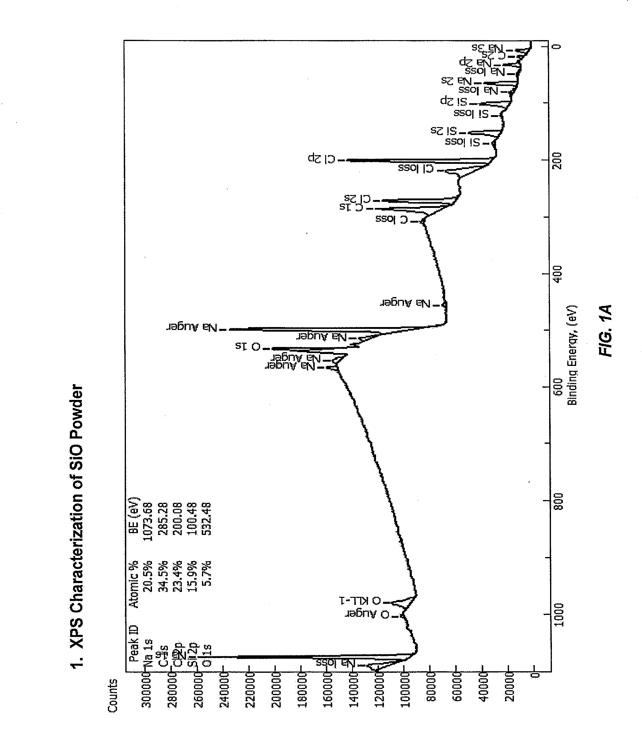
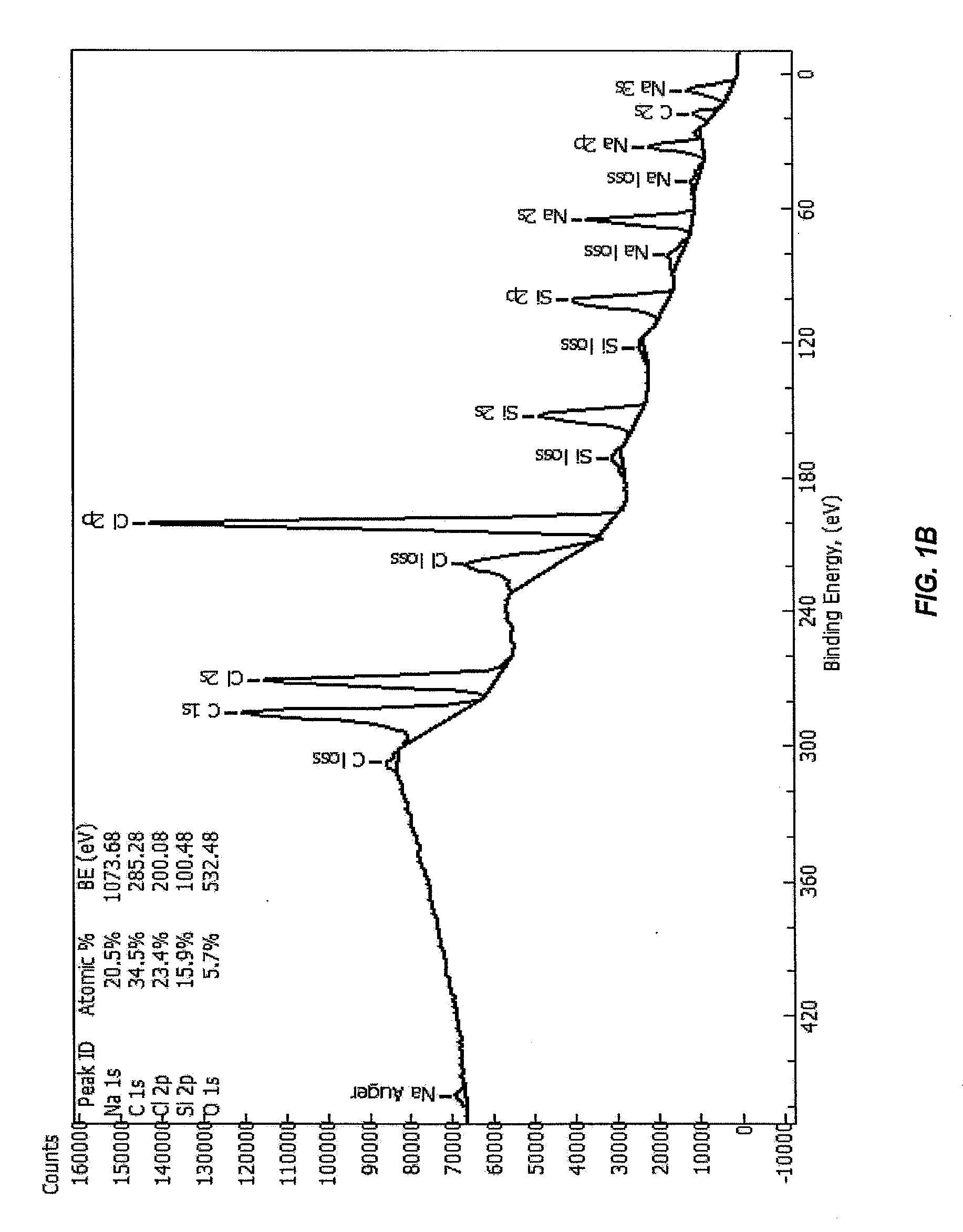
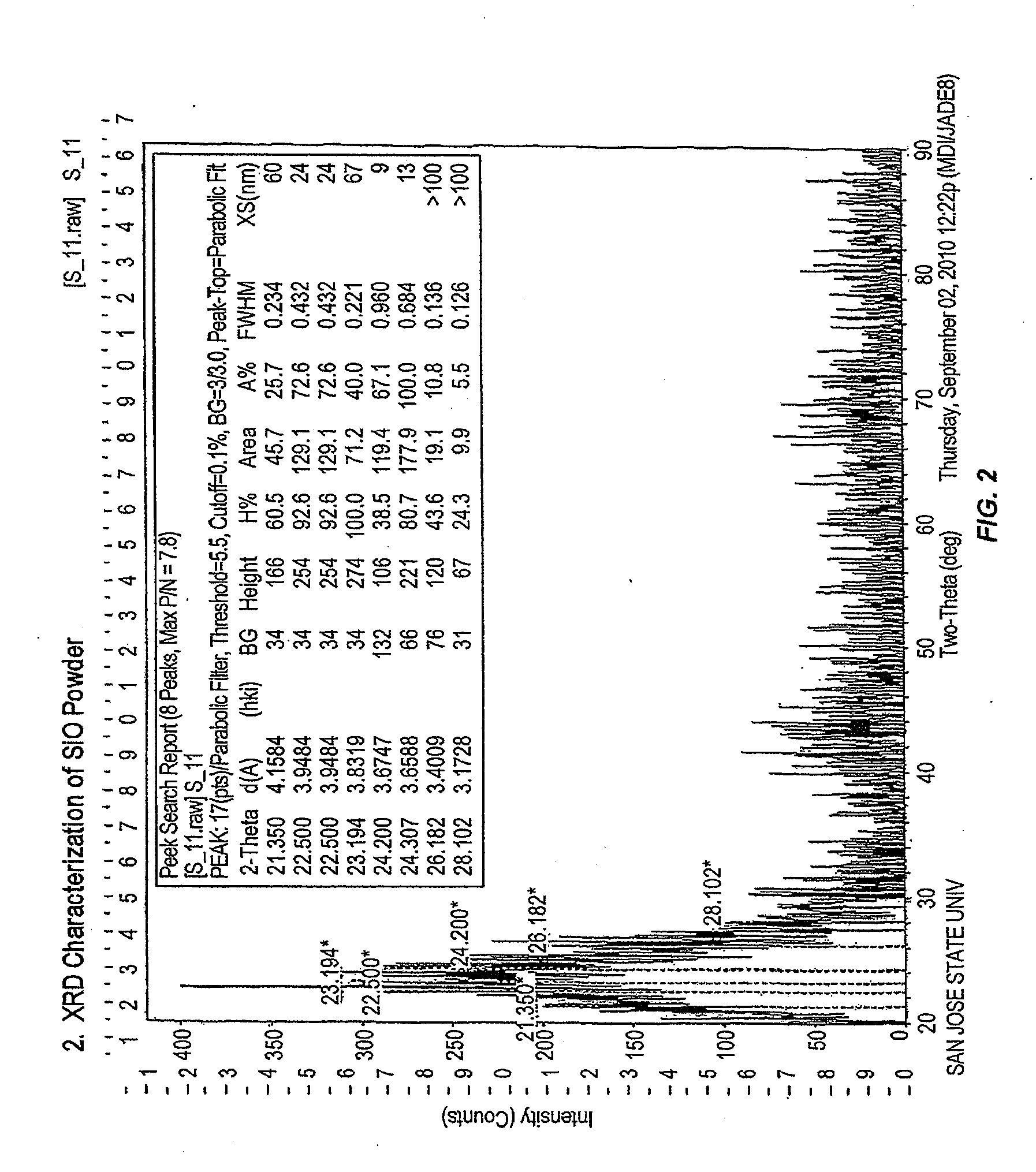
Synthesis of Silicon Monoxide Anode Material
[0126]The first steps are conducted in a glove box under an argon atmosphere. Sodium naphthalide solution is prepared by mixing sodium metal with naphthalene in 1,2-dimethoxyethane (DME) solvent for two hours. A solution of silicon tetrachloride in DME is added, and the combination is poured into a Hastelloy Parr reactor. A vacuum is applied to the reactor so that the pressure is between 150 mTorr and 1 Torr. The temperature of the reactor is adjusted between 200° C. and 400° C. The reaction time varies between 2 hours to 24 hours. After the reaction, the reactor is opened, and alkyl lithium (e.g., methyl lithium) is then added to the solution and mixed overnight to terminate the silicon atoms by an alkyl group.
[0127]The solution is taken out of the glove box to retrieve the alkyl-capped silicon monoxide gel. The DME is removed by evaporation using a rotary evaporator. The resulting gel is then heated at 130° C. in a vacuum oven (i.e., the...
example 2
Synthesis of Mesoporous Silicon
[0130]The first steps are conducted in a glove box under an argon atmosphere. Sodium naphthalide solution is prepared by mixing sodium metal with naphthalene in 1,2-dimethoxyethane (DME) solvent for two hours. A solution of silicon tetrachloride in DME is added, and the combination is mixed overnight. Alkyl lithium (e.g., methyl lithium) is then added to the solution and mixed overnight to terminate the silicon atoms by an alkyl group.
[0131]The solution is taken out of the glove box to retrieve the alkyl-capped silicon monoxide gel. The DME is removed by evaporation using a rotary evaporator. The resulting gel is then heated at 130° C. in a vacuum oven (i.e., the oven temperature was 130° C.) for 8 h to remove naphthalene. The resulting powder is extracted with hexane, and the organic phase is washed six times with water in an extraction funnel to remove sodium and lithium chloride.
[0132]The alkyl-capped silicon is mixed with a spherical nanoparticles ...
example 3
Synthesis of Mesoporous Silicon II
[0133]The first steps are conducted in a glove box under an argon atmosphere. Sodium naphthalide solution is prepared by mixing sodium metal with naphthalene in 1,2-dimethoxyethane (DME) solvent for two hours. A solution of silicon tetrachloride in DME is added, and the combination is poured into a Hastelloy Parr reactor. A vacuum is applied to the reactor so that the pressure is between 150 mTorr and 1 Torr. The temperature of the reactor is adjusted between 200° C. and 400° C. The reaction time varies between 2 hours to 24 hours. After the reaction, the reactor is opened, and alkyl lithium (e.g., methyl lithium) is then added to the solution and mixed overnight to terminate the silicon atoms by an alkyl group.
[0134]The solution is taken out of the glove box to retrieve the alkyl-capped silicon gel. The DME is removed by evaporation using a rotary evaporator. The resulting gel is then heated at 130° C. in a vacuum oven (i.e., the oven temperature w...
PUM
| Property | Measurement | Unit |
|---|---|---|
| particle diameter | aaaaa | aaaaa |
| pore diameter | aaaaa | aaaaa |
| pore diameter | aaaaa | aaaaa |
Abstract
Description
Claims
Application Information