Reducing The Spectral Bandwidth Of Lasers

Active Publication Date: 2014-01-16
KLA TENCOR TECH CORP
View PDF3 Cites 19 Cited by
  • Summary
  • Abstract
  • Description
  • Claims
  • Application Information

AI Technical Summary

Benefits of technology

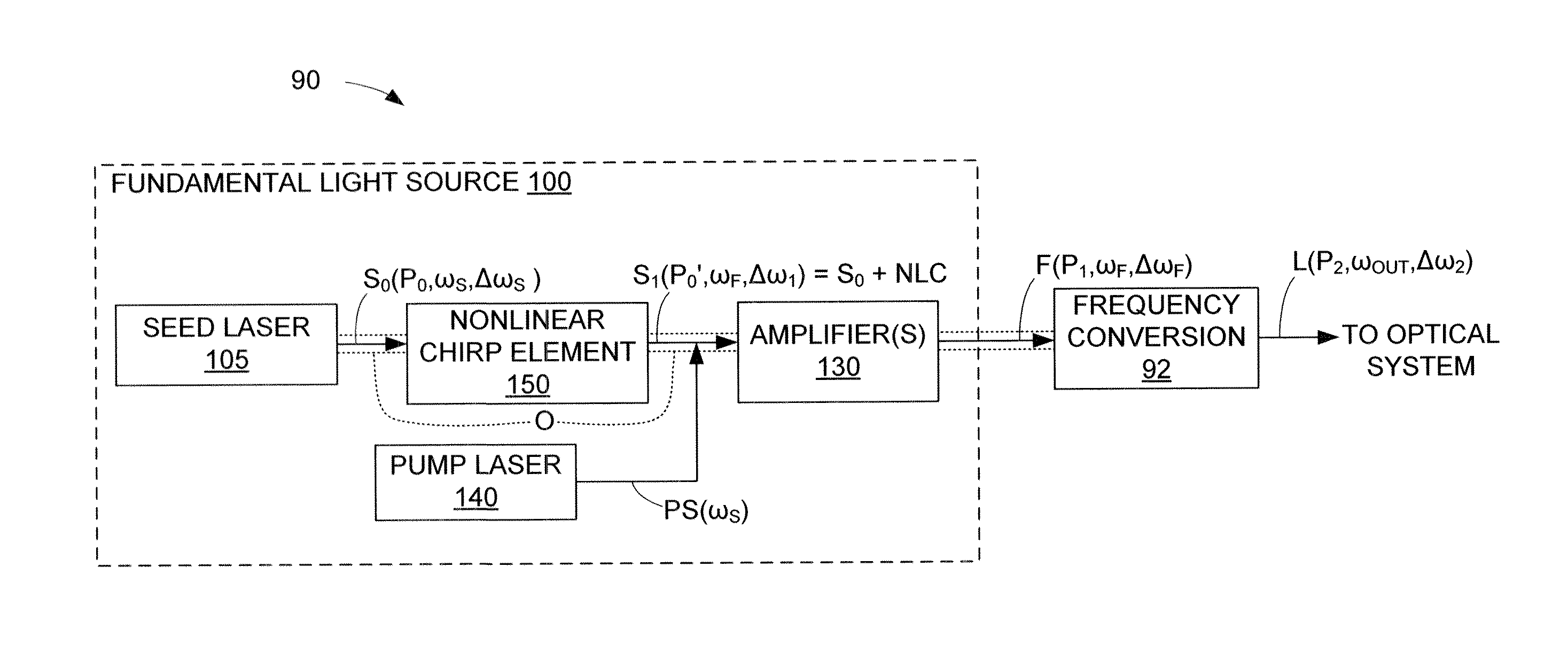
[0018]where T is time, i indicates the imaginary part of the amplitude that contains the phase term, and wherein at least one of one E, F and G is non-zero. The present inventor has determined that a nonlinear chirp having a nonlinearity of x2 or higher is required to achieve fundamental light having a narrow spectral E95 bandwidth that is in a range defined by five times the (initial) spectral E95 bandwidth of the seed light generated by the seed laser (e.g., in the range of 1 and 100 GHz). By way of comparison, a linear chirp generated in a manner similar to that used in the present invention (e.g., using a Bragg grating configured to generate a linear chirp) is capable of generating a FWHM value that is close to that of the seed light, but its E95 bandwidth is over ten times higher. Accordingly, the SPM characteristics generated by a fiber-based amplifier (e.g., either a doped fiber amplifier or a fiber Raman amplifier) require an x2 or higher nonlinearity (e.g., that at least one of E, F and G in the above equation must be non-zero) to adequately compensate for SPM characteristics to the degree required by high resolution laser inspection systems. According to an embodiment, a single nonlinear chirp element is positioned in the laser optical path between the seed laser and a series of fiber amplifiers, wherein the nonlinear chirp element is configured to generate a single nonlinear chirp that compensates for the cumulativ

Problems solved by technology

A significant obstacle to the development of short wavelength UV-DUV laser inspection systems is to provide an optical system that can effectively image the UV laser light.
Optical systems manufactured from all fused silica for use in systems using UV-DUV laser light can only handle a limited bandwidth before the performance degrades beyond acceptable limits.
However the increased cost and complexity associated with the use of aspheric surface may not be desirable, and this approach only helps a small amount in most laser systems.
It is also possible to perform the frequency conversion/mixing process using other nonlinear processes (e.g., Raman, parametric generation, and four wave mixing (FWM)), but these techniques can also lead to increased bandwidths and not be suitable for narrow bandwidth optics.
Many stages of frequency conversion/mixing are sometimes needed to gen

Method used


Image

  • Reducing The Spectral Bandwidth Of Lasers
  • Reducing The Spectral Bandwidth Of Lasers
  • Reducing The Spectral Bandwidth Of Lasers

Examples


Embodiment Construction

[0033]The present invention relates to an improvement in laser technology. The following description is presented to enable one of ordinary skill in the art to make and use the invention as provided in the context of a particular application and its requirements. As used herein, directional terms such as “higher”, “lower”, “front” and “downstream” are intended to provide relative positions for purposes of description, and are not intended to designate an absolute frame of reference. Various modifications to the preferred embodiment will be apparent to those with skill in the art, and the general principles defined herein may be applied to other embodiments. Therefore, the present invention is not intended to be limited the particular embodiments shown and described, but is to be accorded the widest scope consistent with the principles and novel features herein disclosed.

[0034]FIG. 3 shows a laser system 90 according to a generalized embodiment of the present invention. Laser system ...


PUM


Abstract

A laser system for semiconductor inspection includes a fiber-based fundamental light source for generating fundamental light that is then converted/mixed by a frequency conversion module to generate UV-DUV laser light. The fundamental light source includes a nonlinear chirp element (e.g., a Bragg grating or an electro-optic modulator) that adds a nonlinear chirp to the seed light laser system prior to amplification by the fiber amplifier(s) (e.g., doped fiber or Raman amplifiers). The nonlinear chirp includes an x2 or higher nonlinearity and is configured to compensate for the Self Phase Modulation (SPM) characteristics of the fiber-based amplifiers such that fundamental light is generated that has a spectral E95 bandwidth within five times that of the seed light. When multiple series-connected amplifiers are used, either a single nonlinear chirp element is provided before the amplifier string, or chirp elements are included before each amplifier.

Description

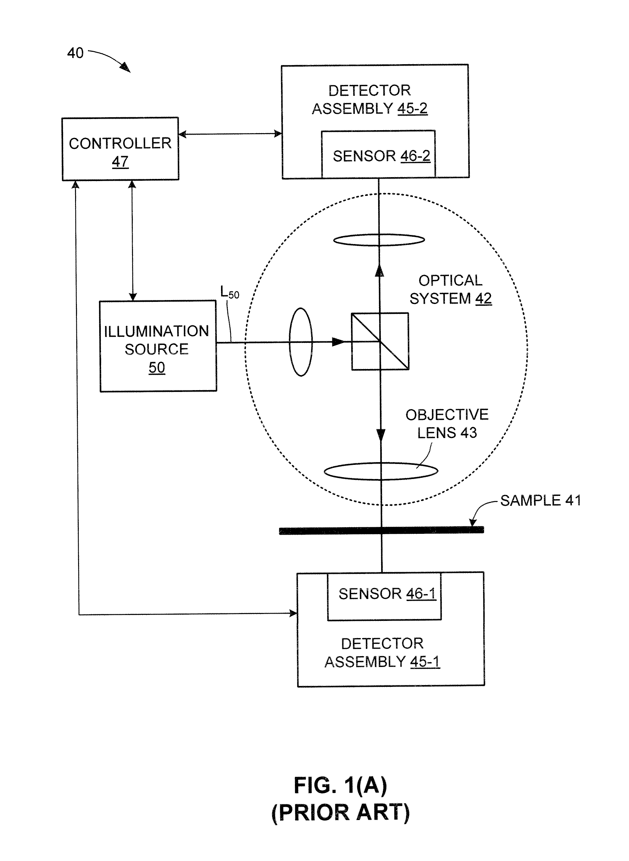
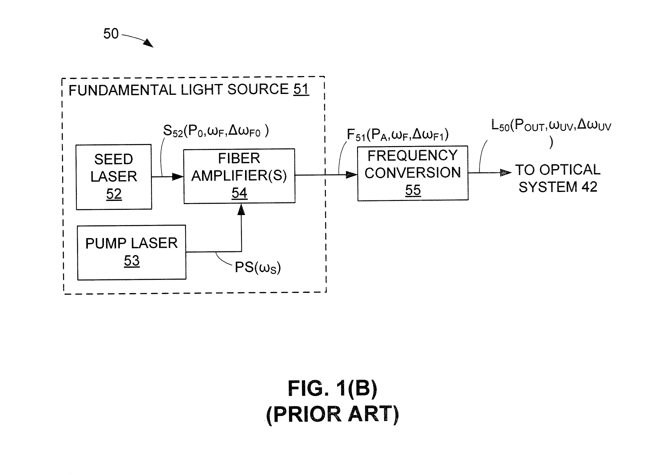
RELATED APPLICATIONS[0001]This application claims priority to U.S. Provisional Patent Application 61 / 670,926, entitled “Reducing The Spectral Bandwidth Of Lasers” filed Jul. 12, 2012.BACKGROUND OF THE INVENTION[0002]1. Field of the Invention[0003]The present invention generally relates to illuminators used in conjunction with inspection systems, such as semiconductor wafer inspection systems and photomask inspection systems, and more particularly to a fiber amplifier based light source for use with such inspection systems.[0004]2. Description of the Related Art[0005]FIG. 1(A) is a diagram depicting a simplified UV-DUV laser inspection system 40 utilized in the semiconductor industry for inspecting a target sample (e.g., a wafer or photomask / reticle) 41. Inspection system 40 includes an illumination source 50 that generates laser light L50 typically in the UV-DUV range (e.g., a vacuum wavelength less than 350 nm), an optical system 42 including one or more objective lenses 43 that fo...

Claims


Application Information

Patent Timeline
IPC IPC(8): H01S3/10H01S3/30H01S3/02
CPCH01S3/10H01S3/02H01S3/30H01S3/06758H01S3/302H01S3/0057H01S3/0092H01S2301/08G01N21/9501G01N21/956G01N21/00H01S3/06754
Inventor ARMSTRONG, J. JOSEPH
Owner KLA TENCOR TECH CORP
Why Eureka
Try Eureka