
Solar heat storage and high temperature gas generating system with working medium being flowing sand

Inactive Publication Date: 2014-01-30
CHEN YUQI
View PDF2 Cites 12 Cited by
  • Summary
  • Abstract
  • Description
  • Claims
  • Application Information

AI Technical Summary

Benefits of technology

This patent aims to provide systems that use solar energy to store and generate heat using a flowing sand as a medium. These systems have advantages such as better thermal energy storage, larger scale of heat storage, higher efficiency for heat exchange, and lower manufacture and operation costs.

Problems solved by technology

In order to achieve large-scale application of solar energy, two key issues are solar energy storage and reduce operating costs.
One advantage of liquid media is that its liquidity is very good while the problems are that when the volume is large, the container has to endure higher lateral pressure at a high temperature, resulting in a high cost.
In addition, molten metal salt has a corrosion problem, and the heat conduction oil and sodium metal are quite expensive.
Moreover, for sodium metal, it is not easy to prevent leakage, resulting in security issues.
These shortcomings result in that liquid-storage media are too expensive to be used in thermal energy storage systems.
Solid thermal storage media, such as rock, soil, concrete, with advantages being low cost, have disadvantage of poor liquidity, which lead to heat exchange difficult.
(1) The collector did not consider solar concentrator, so that the energy losses by convection and radiation are large due to large exposed area. Therefore, the highest temperature of the heated particulate matter cannot be too high to be applied directly to the high-temperature solar thermal system and thus cannot be used to effectively power or as an industrial power.
(2) Sand surface is usually light colors, when directly used to absorb sunlight, high reflection rate of sunlight leads to larger energy losses and lower efficiency.
(3) Only a simple cylindrical heat storage tank is given. When its volume is increased, side walls withstand very high pressure in the horizontal direction along the walls. To overcome it, one has to increase the wall thickness. It results in increase of the heat stress, manufacture costs so that one is not able to produce low-cost thermal storage tank. Usually, to a fluid, within a container, the sidewall grazing pressure is proportional to the ratio of the diameter and the thickness of the container. In this way, while the height keeps the same but diameter increases, in order to maintain the vessel's endurance, it is bound to increase the thickness of the container, which makes the cost of per unit area increase. Moreover, when the container's height increases, the bottom of the container withstands more radial pressure to the fluid, making further increases the cost per unit area. Therefore, usually to fluid, when container's volume increases, unit costs per volume increases instead of decreases. That is, usually to the gas or liquid fluids, on the one hand, any container cannot be made big, on the other hand, if making big, the cost becomes more per unit of volume. Storage containers for powder material such as sand, if the inside wall along the cylinder axis is straight, the conclusion is similar.
(4) The proposed heat exchanger transfer heat between the fluidized-bed granular material and fluid in the pipe. Since pipes and air contact directly, heat transfer is inefficiencies. For these reasons, in accordance with U.S. Pat. No. 4,338,919 proposed methods and devices high temperature and high pressure gas could not be produced efficiently so as to drive the turbine system.
Currently, costs of the trough solar concentrator, the tower solar concentrator, and the dish solar concentrator are very expensive.
Trough concentrating system uses single-axis tracking, supporting and driving system for tracking, so the price is low, but the cost is expensive in vacuum glass tubes used; if the Tower type and disc type dual-axis tracking solar concentrator used, the support and track-drive parts are expensive.
Based on the principle of solar concentrator, the costs are high, resulting in limiting the widespread use of solar concentrator.
They cannot be used to exchange heat between sand and liquid or between sand and gas.

Method used


Image

  • Solar heat storage and high temperature gas generating system with working medium being flowing sand
  • Solar heat storage and high temperature gas generating system with working medium being flowing sand
  • Solar heat storage and high temperature gas generating system with working medium being flowing sand

Examples


Embodiment Construction

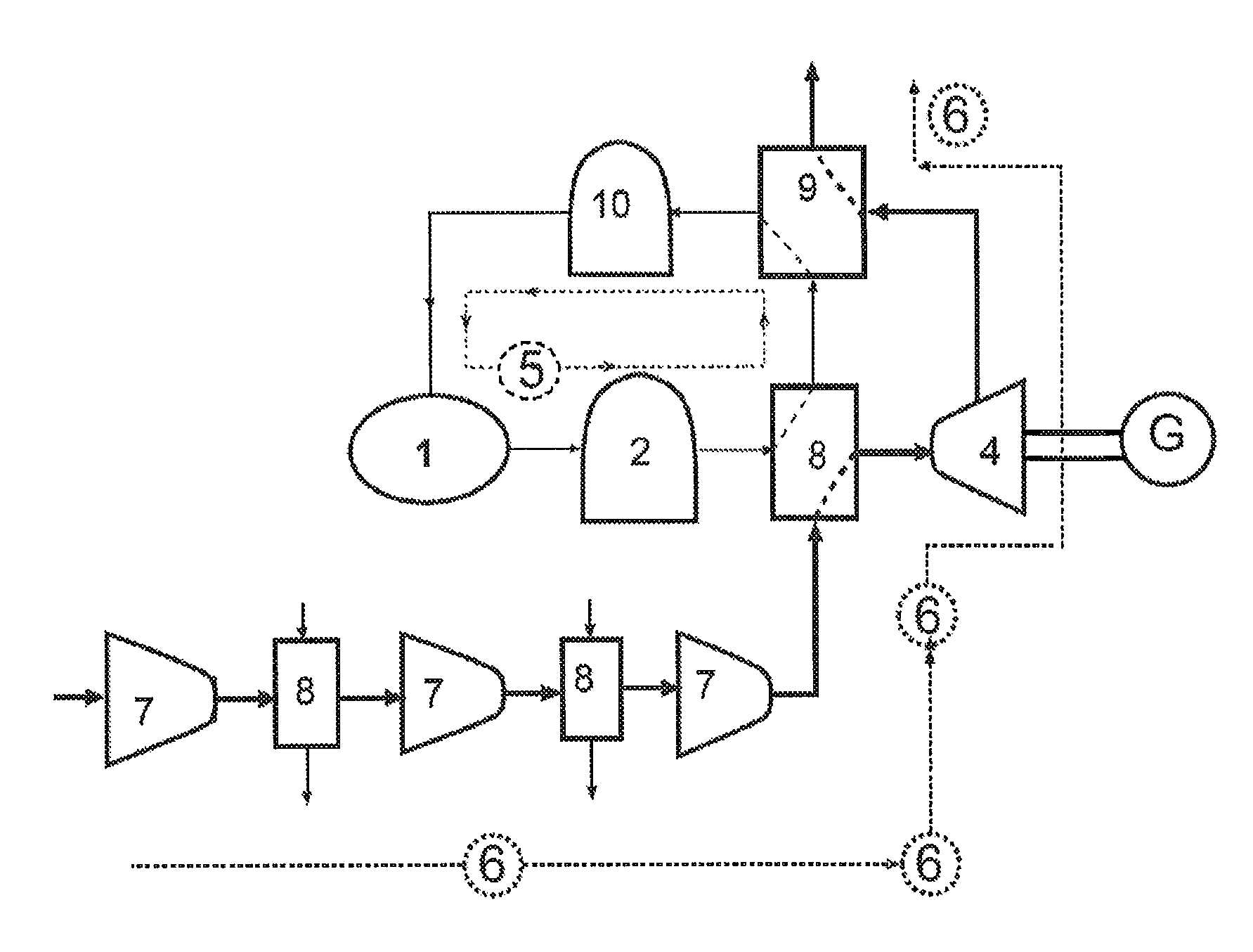
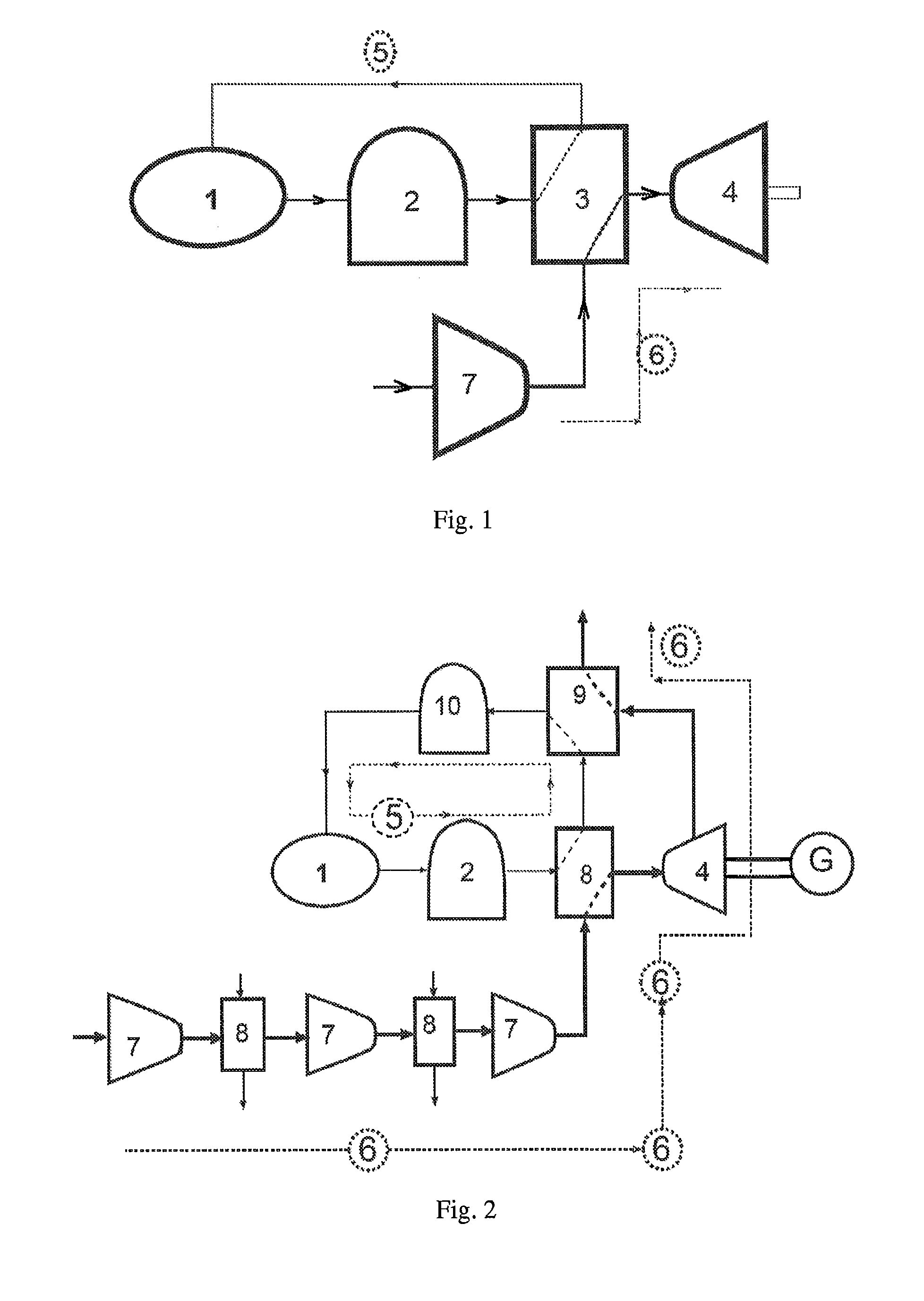
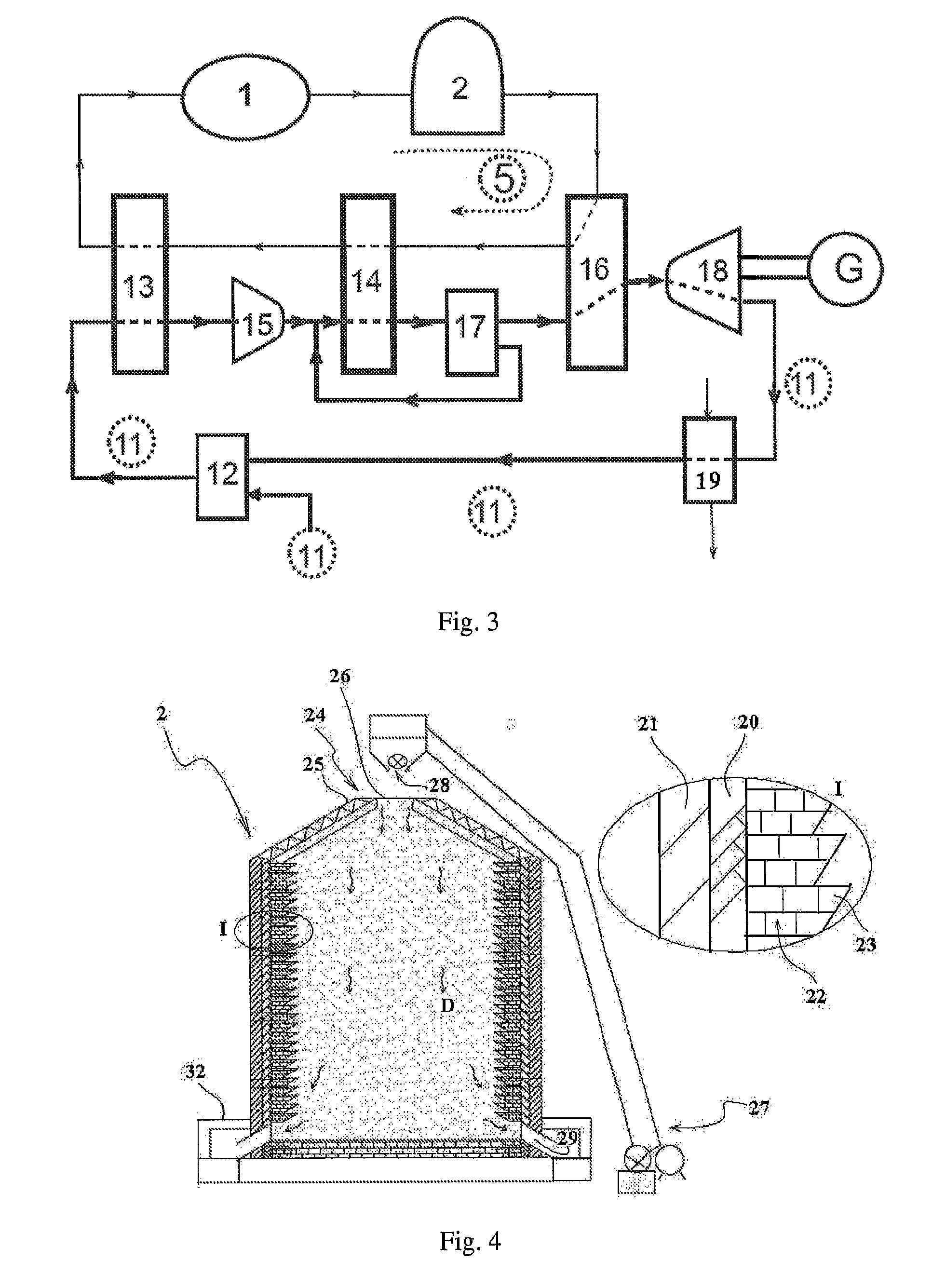
[0047]Utilizing sand's solidity, fluidity, high temperature resistance, corrosion resistance, low-cost, especially being able to be stacked, this invention provides to build solar heat energy storage tank which is of large capacity, of being able to long-term storage with flowing sand as energy storage materials and work medium. The heat storage tank allows sunlight heat sand to high temperature by intermittently input but by continuous and stable output. Addition to the sand, the invention is equally suitable for all other particulate matter and their mixtures with similar properties as flowing sand, i.e., solidity, fluidity, high temperature resistance, corrosion resistance, low-cost, especially those particulate matter and their mixtures which are able to be stacked.

[0048]According to one aspect of the present invention, as shown in FIG. 1, it provides a method and system to generate steady, high temperature, and high pressure gas to drive turbines 4 for generating power or for i...


PUM


Abstract

A solar heat storage and high temperature gas generating system comprises a sun-tracking light concentrating device (1), a heat storage tank (2) and a heat exchange device (3), with the working medium being flowing sand (5). The flowing sand (5) is heated by the sun-tracking light concentrating device (1), and is transported into the heat storage tank (2). The flowing sand (5) is exported from the heat storage tank (2) steadily, thereby transferring heat to the high pressure gas or liquid (6) which is to be heated in the heat exchange device (3) and generating high temperature and pressure gas. The system has the advantages of good heat storage effect, large heat storage volume, high heat exchange efficiency and low operation cost.

Description

TECHNICAL FIELD[0001]The present invention is related to a system and a method to store solar energy, in addition, the invention deals with a system and a method of storage of solar-generated hot gas. In particular, the invention relates to systems for solar heat storage and high temperature gas generation with flowing sand as medium.PRIOR ART[0002]In order to achieve large-scale application of solar energy, two key issues are solar energy storage and reduce operating costs. Heated medium by solar concentrator can produce high temperature and high pressure gas (such as air or steam), driving turbines turbine power generation or for industrial use.[0003]In the solar photo-thermal systems, the solar energy is stored in a form of thermal energy. It is known as the best way to store solar energy. However, to achieve low cost, long-lasting, mass thermal storage, it is critical to find out storage medium that is cheaper, high-temperature resistant, and easy to realize heat of exchange.[00...

Claims


Application Information

Patent Timeline
IPC IPC(8): F24J2/38F24S10/95F24S20/20F24S23/70F24S23/72F24S50/20
CPCF24J2/38F28C3/14F28D1/0477F28D1/05316F28D13/00F28D20/0056C09K5/14Y02E10/46Y02E70/30F03G6/067F28F13/06F28D7/00Y02E10/47F24S80/20F24S23/72F24S20/20F24S30/425F24S30/452F24S10/95Y02E60/14Y02P20/10Y02E10/44F24S50/20Y02E10/40
Inventor CHEN, YUQI
Owner CHEN YUQI
Learn More