High power converter architecture

a converter and high-power technology, applied in the direction of electric variable regulation, process and machine control, instruments, etc., can solve the problems of increasing the relative high voltage and current and the corresponding increase in the stress on the switching component. to achieve the effect of increasing the leakage inductan

Active Publication Date: 2014-01-30
FLEXTRONICS AP LLC
View PDF2 Cites 18 Cited by
  • Summary
  • Abstract
  • Description
  • Claims
  • Application Information

AI Technical Summary

Benefits of technology

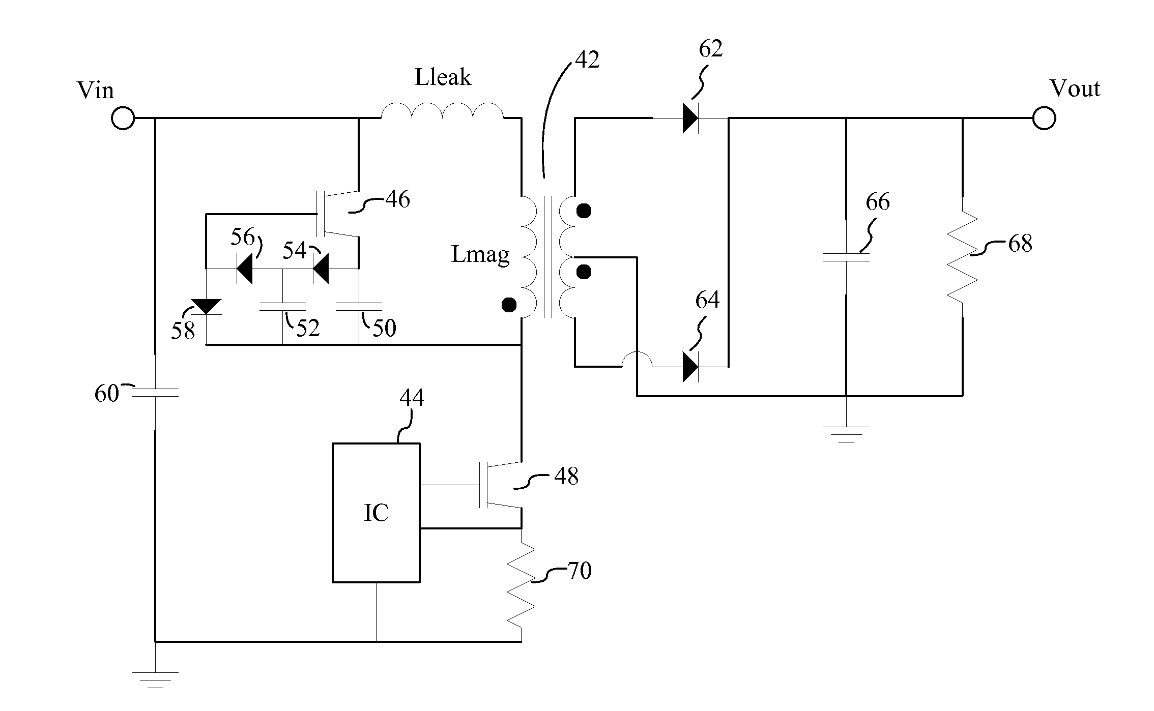
[0016]In some embodiments, the power converter circuit is configured to forward energy from the input supply voltage to the output circuit when the primary switch is ON. In some embodiments, the parasitic capacitances include parasitic capacitances from the auxiliary switch and the primary switch. In some embodiments, the resonant energy is delivered over an entire resonant cycle of the resonant tank, wherein the resonant tank includes the primary winding and the resonant cycle includes a positive primary winding current flow and a negative primary winding current flow. In some embodiments, energy delivered to the output load includes a summation of energy forwarded from the input supply, resonant energy stored and released by the resonant tank, and parasitic capacitances and leakage inductance stored and released as additional resonant energy by the resonant tank. In some embodiments, the auxiliary switch is a parametrically controlled auxiliary switch. In some embodiments, the power converter circuit also includes driving circuitry coupled to the auxiliary switch and to the primary switch, wherein the driving circuitry is configured to parametrically control the auxiliary switch according to a voltage condition of the primary switch. In some embodiments, the resonant circuit, the transformer, and the output circuit are configured to store and release the resonant energy and the additional resonant energy according to a flyback mode of energy conversion. In some embodiments, during the flyback mode of energy conversion, the primary switch is OFF. In some embodiments, the output circuit includes a first diode, a second diode, and a capacitor, wherein the first diode and the second diode are coupled to the secondary winding of the transformer such that when the first diode is forward biased, the second diode is reverse biased, and when the first diode is reverse

Problems solved by technology

However, an increase in switching frequency can cause a corresponding increase in switching and component stress related losses, as well as increased electromagnetic interference (EMI), noise, and switching commutation problems, due to the rapid ON/OFF switching of the semiconductor switches at high voltage and/or high current levels.
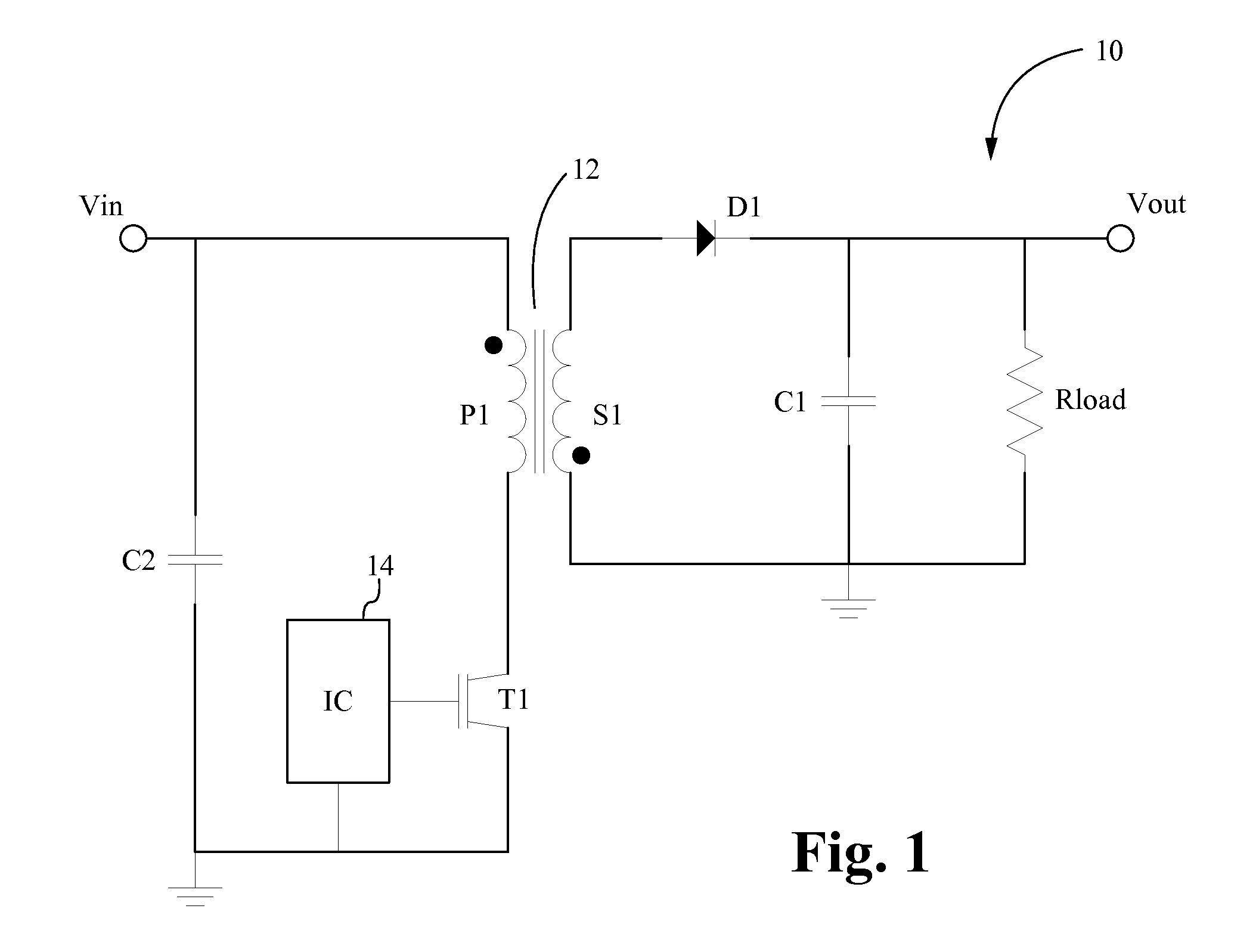
However, in the flyback converter, the primary and secondary windings of the transformer do not carry current simultaneously.
A drawback to use of the flyback is the relatively high voltage and current stress suffered by the switching components.
Additionally, high turn-off voltage (caused by the parasitic oscillation between transformer leakage inductance and switch capacitance) seen by the primary switch traditionally requires the use of a resistor, capacitor, diode subcircuit, such as a snubb

Method used


Image

  • High power converter architecture
  • High power converter architecture
  • High power converter architecture

Examples


Embodiment Construction

[0027]Embodiments of the present application are directed to a power converter. Those of ordinary skill in the art will realize that the following detailed description of the power converter is illustrative only and is not intended to be in any way limiting. Other embodiments of the power converter will readily suggest themselves to such skilled persons having the benefit of this disclosure.

[0028]Reference will now be made in detail to implementations of the power converter as illustrated in the accompanying drawings. The same reference indicators will be used throughout the drawings and the following detailed description to refer to the same or like parts. In the interest of clarity, not all of the routine features of the implementations described herein are shown and described. It will, of course, be appreciated that in the development of any such actual implementation, numerous implementation-specific decisions must be made in order to achieve the developer's specific goals, such...


PUM


Abstract

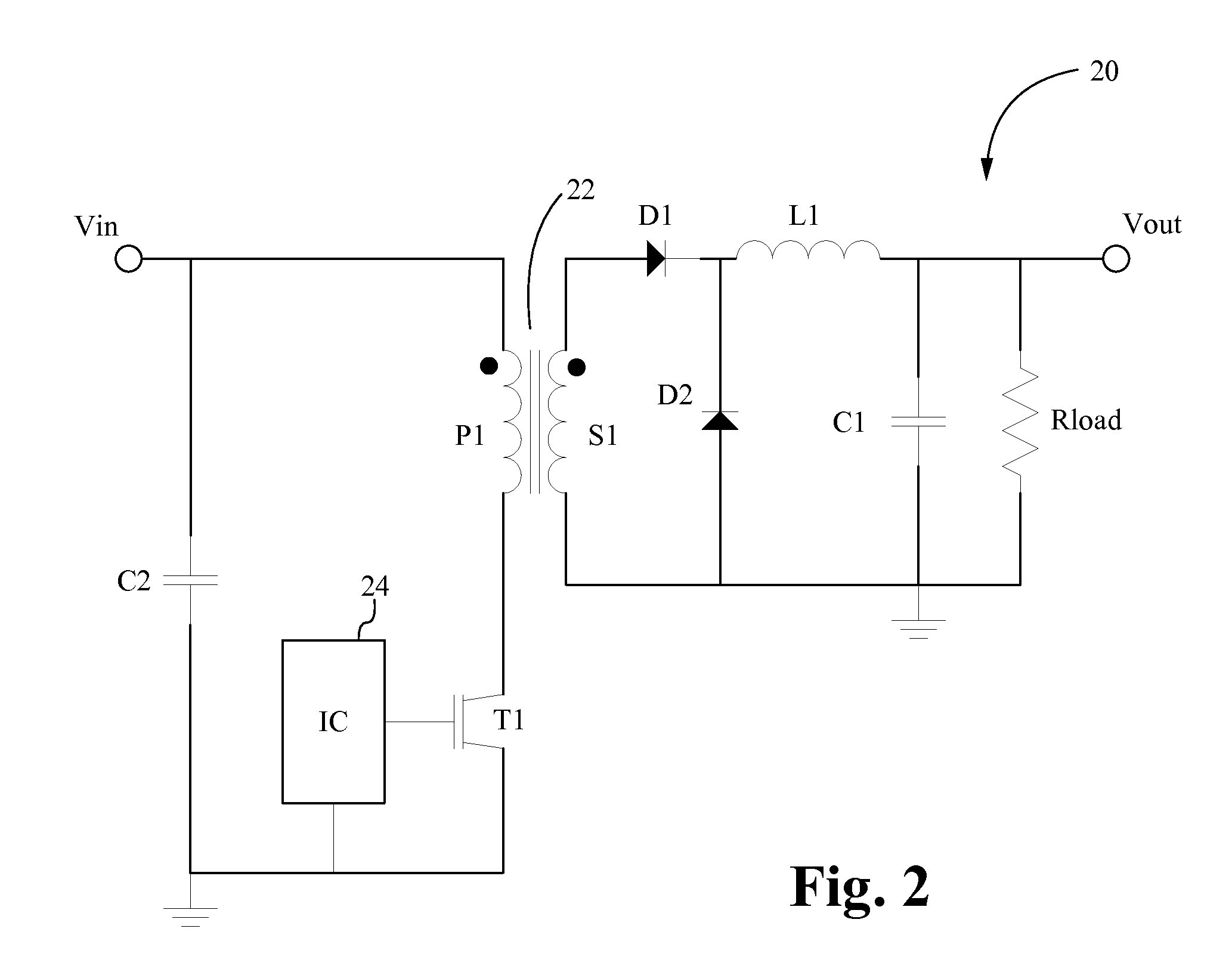
The power converter is an integration of three topologies which include a forward converter topology, a flyback converter topology, and a resonant circuit topology. The combination of these three topologies functions to transfer energy using three different modes. A first mode, or forward mode, is a forward energy transfer that forwards energy from the input supply to the output load in a manner similar to a forward converter. A second mode, or flyback mode, stores and releases energy in a manner similar to a flyback converter. A third mode, or resonant mode, stores and releases energy from the resonant tank using a resonant circuit and a secondary side forward-type converter topologies.

Description

FIELD OF THE INVENTION[0001]The present invention is generally directed to the field of power converters. More specifically, the present invention is directed to a new power converter architecture having increased efficiency.BACKGROUND OF THE INVENTION[0002]There are several power converter topologies that have been developed over the years, which are intended to improve the power density and switching efficiency of power converters. An emerging focus of new converter topologies is to provide a means to reduce or eliminate converter switching losses, while increasing the switching frequencies. Lower loss and higher switching frequency means more efficient converters, which can reduce the size and weight of converter components. Additionally, with the introduction of high speed composite semiconductor switches, such as metal oxide semiconductor field effect transistor (MOSFET) switches operated by pulse width modulation (PWM), recent forward and flyback topologies are now capable of ...

Claims


Application Information

Patent Timeline
IPC IPC(8): H02M3/335
CPCH02M3/33523Y02B70/10H02M1/342
Inventor TELEFUS, MARK
Owner FLEXTRONICS AP LLC
Why Eureka
Try Eureka