Olefin conditioning in a fast catalytic pyrolysis recycle process

a technology of pyrolysis and olefin conditioning, which is applied in the direction of carboxylic compound preparation, ether preparation, thermal non-catalytic cracking, etc., can solve the problems of thermal instability, liquid product mixture, and inability to meet the requirements of the app nor the syngas process, so as to reduce the formation of char and increase the production of useful products

a technology of pyrolysis and olefin conditioning, which is applied in the direction of carboxylic compound preparation, ether preparation, thermal non-catalytic cracking, etc., can solve the problems of thermal instability, liquid product mixture, and inability to meet the requirements of the app nor the syngas process, so as to reduce the formation of char and increase the production of useful products

US20140031583A1Inactive Publication Date: 2014-01-30ANELLOTECH INC

Image

  • Olefin conditioning in a fast catalytic pyrolysis recycle process
  • Olefin conditioning in a fast catalytic pyrolysis recycle process
  • Olefin conditioning in a fast catalytic pyrolysis recycle process

Examples


Embodiment Construction

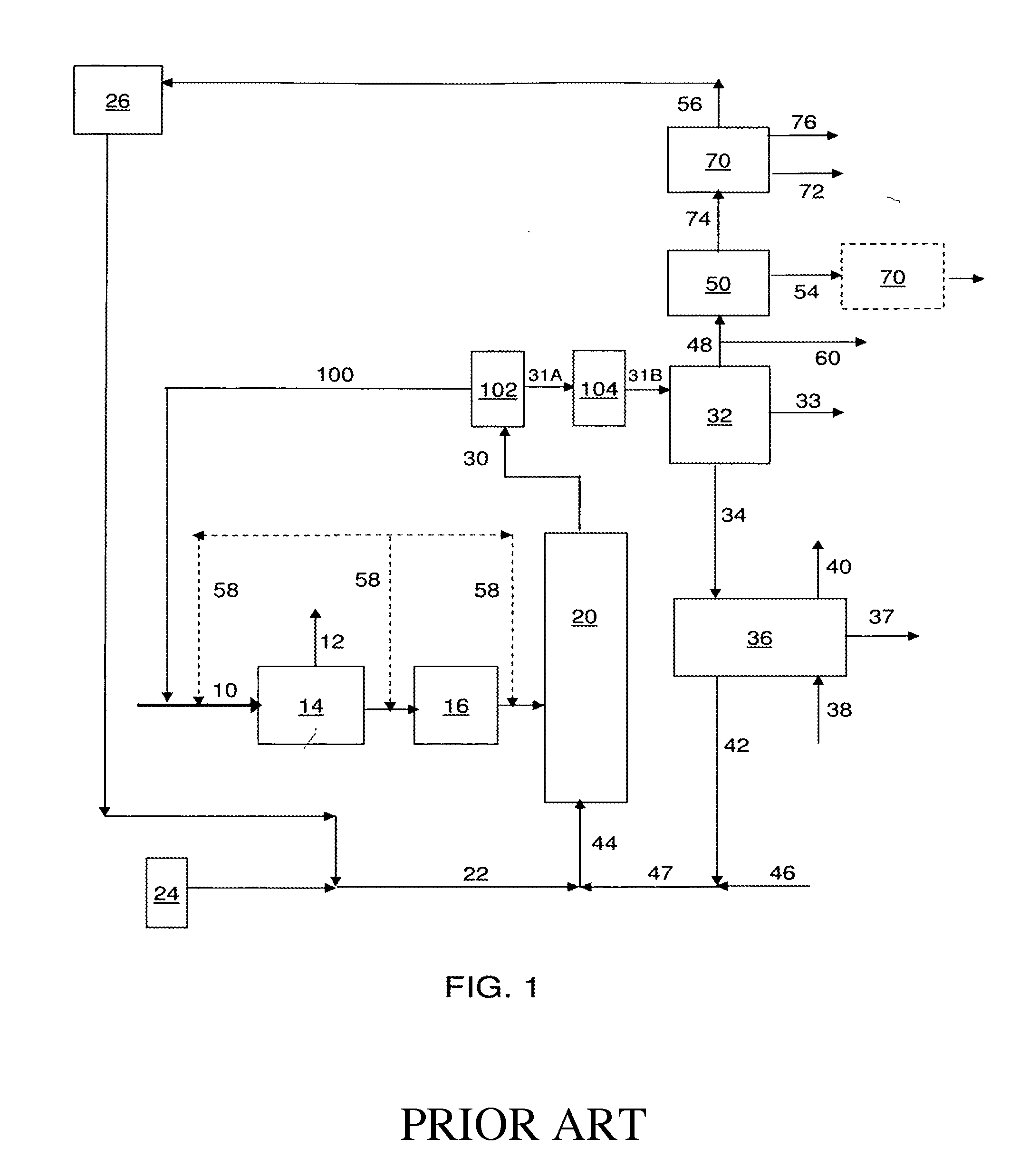
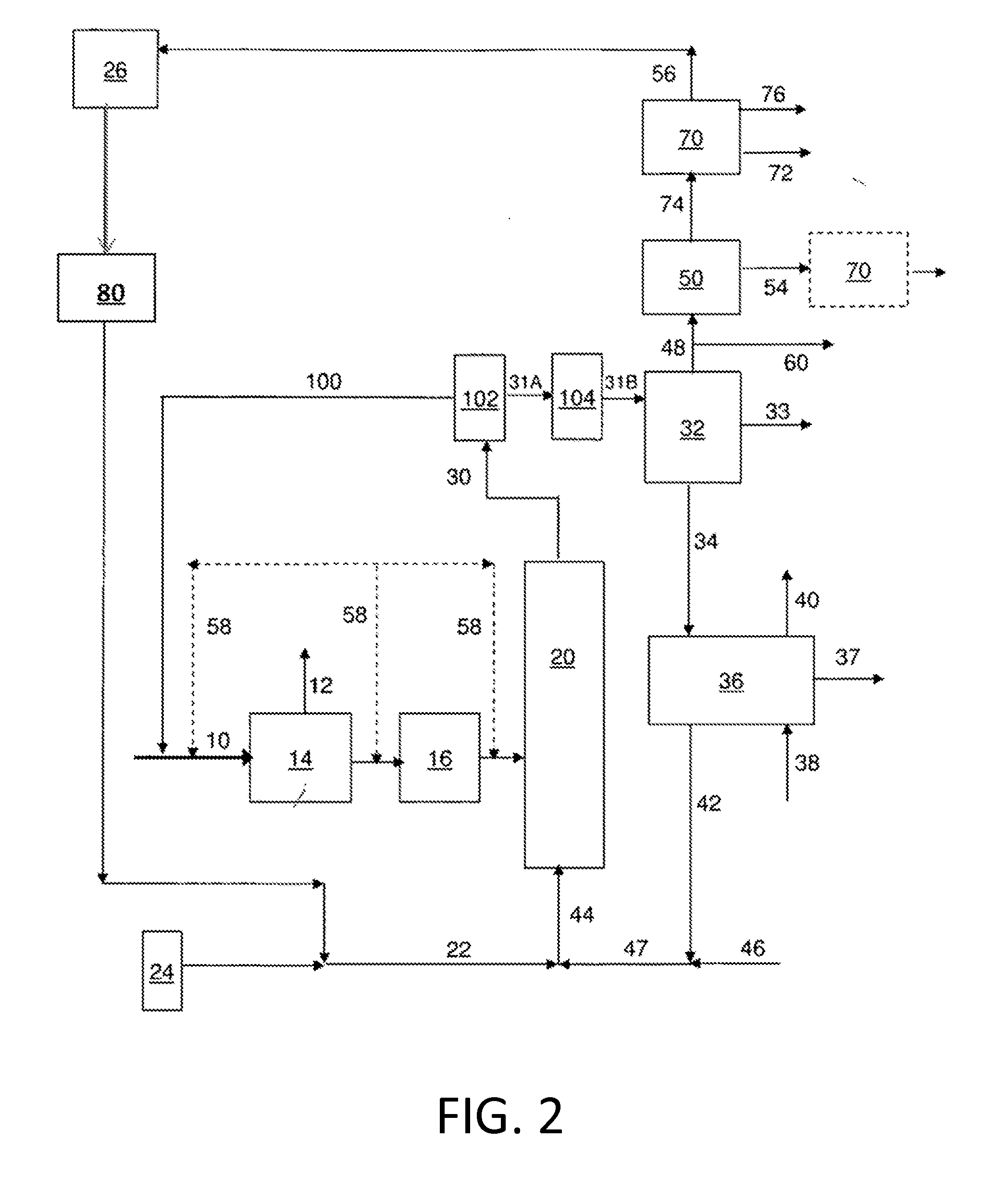
[0065]Since olefins are commonly produced, the invention is generally applicable to any biomass pyrolysis reaction. Preferably, the biomass feedstock comprises a solid hydrocarbonaceous material. The biomass feedstock may comprise, for example, any one or combination of the biomass sources that are mentioned in the Glossary section. The pyrolysis reactor can be without a solid catalyst; however, preferably, the pyrolysis reactor comprises a solid catalyst for fast catalytic pyrolysis (FCP). The type of reactor and the type of solid catalyst (if present) are not limited, and can be generally of the type known for conversion of biomass to fluid hydrocarbonaceous streams. Examples of suitable apparatus and process conditions for FCP are described in the patent application of Huber at al. [US20090227823] that is incorporated herein by reference. Conditions for FCP of biomass can be selected from any one or any combination of the following features (which are not intended to limit the br...


PUM

PropertyMeasurementUnit
Temperatureaaaaaaaaaa
Fractionaaaaaaaaaa

Abstract

This invention relates to improvements in the fast pyrolysis of biomass. In this invention, olefins are separated from the effluent stream of a pyrolysis reactor and at least a portion of the olefins are treated and the resulting treated stream recycled to the pyrolysis reactor for further conversion to valuable, useful products.

Description

RELATED APPLICATION[0001]This application claims the benefit of priority U.S. provisional patent application Ser. No. 61 / 676,840, filed Jul. 27, 2012.INTRODUCTION[0002]Due to its cost and wide availability, lignocellulosic biomass is under worldwide-study as a viable feedstock for renewable liquid biofuels and chemicals because of its low cost and wide availability. Biomass-derived fuels and chemicals substantially reduce net CO2 emissions if produced with minimal use of fossil fuels. However, lignocellulosic biomass is not currently commonly used as a liquid fuel or chemicals source because typical current conversion processes are not considered to be economically viable. Several routes are being examined to convert solid biomass to valuable liquid fuels and chemicals. At low temperatures (e.g., 200-260° C.) diesel range alkanes can be produced by a multi-step, aqueous-phase processing (APP) of aqueous carbohydrate solutions involving dehydration, aldol-condensation and dehydration...

Claims


Application Information

Patent Timeline
30 Jan 2014
Publication
US20140031583A1
IPC
C10G1/00; C07C41/06; C07C51/14; C07C37/00
CPC
C10G1/002; C07C51/14; C07C41/06; C07C37/00; C10B53/02; C10B57/06; C10G1/08; C10G3/00
Inventors
MAZANEC, TERRY; WHITING, JEFF