Optical Systems

a technology of optical systems and optical components, applied in optics, laser details, laser devices, etc., can solve the problems of unsustainable, high amplifier gain, and inability to produce high noise levels between pulses, so as to prevent q-switching or excessive ase development, reduce the effect of high amplifier gain and large selectable modulation ra

Active Publication Date: 2014-02-20
NKT PHOTONICS
View PDF8 Cites 67 Cited by
  • Summary
  • Abstract
  • Description
  • Claims
  • Application Information

AI Technical Summary

Benefits of technology

[0129]In one aspect, the present invention provides a method of having a MOPA laser system with an extremely large range of selectable modulation rate. The modulation can be achieved without high levels of amplified noise (Amplified Spontaneous Emission) and/or without the need for external modulation. In certain practices, the approach can ensure that the amplifier is seeded at a relatively constant power level, sufficient to prevent Q-switching or excessive ASE development, and/or operates at a relatively constant gain (so constant output peak power) yet enables the combined laser MOPA to deliver variable repetition rate, user selectable from single shot to the fundamental frequency of the oscillator without having to rely on pump power modulation. Note—constant gain and seed level are not obligatory but a satisfactory seed and gain level can usually be maintained to avoid the effects of self-Q-switching an

Problems solved by technology

Direct modulation of a fiber or solid state amplifier is limited in the switching speed due to carrier lifetimes within the amplifier gain media.
For low pulse repetition rates, the duty cycle of the pulses can be insufficient to saturate the amplifier, resulting in the amplifier producing high noi

Method used


Image

  • Optical Systems
  • Optical Systems
  • Optical Systems

Examples


example 2

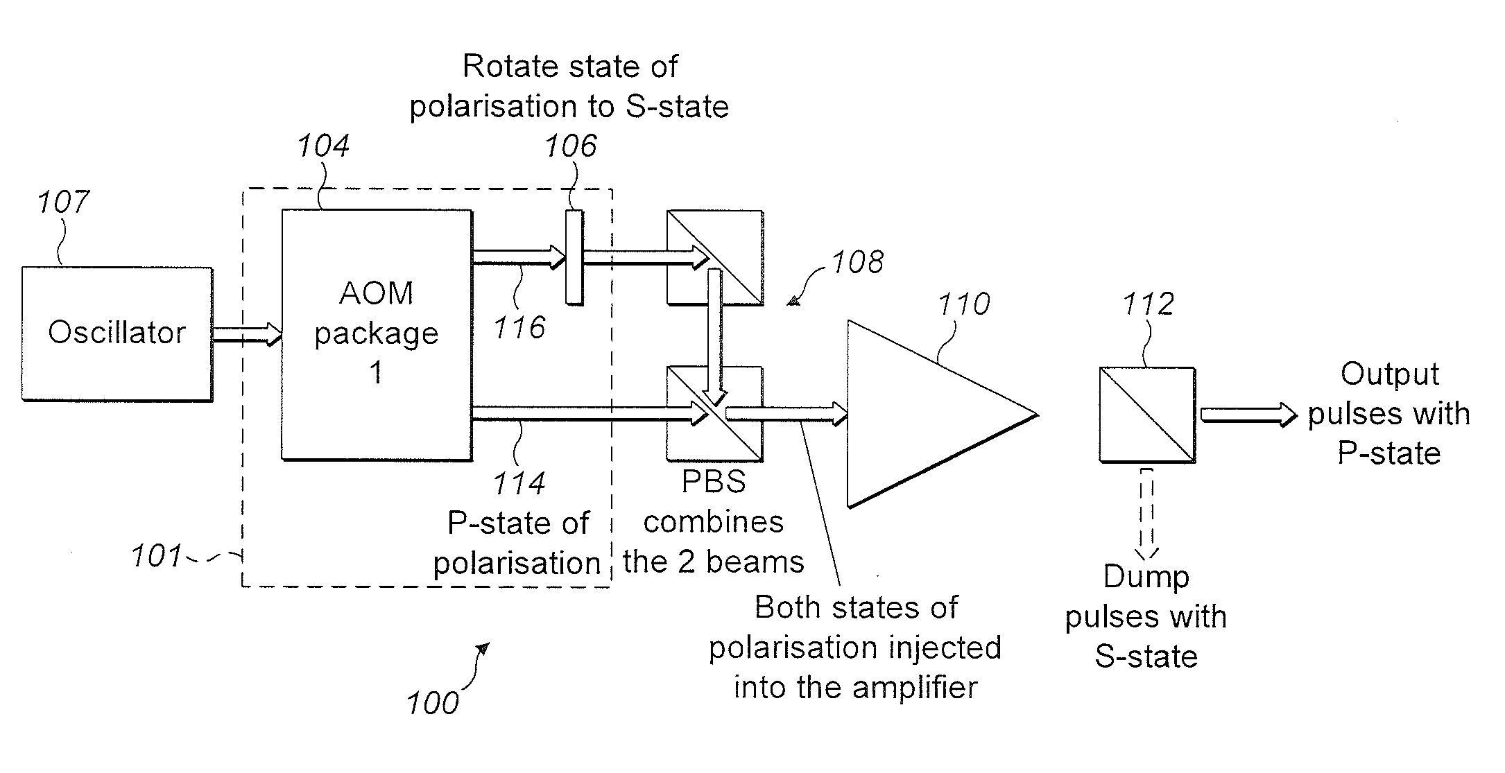
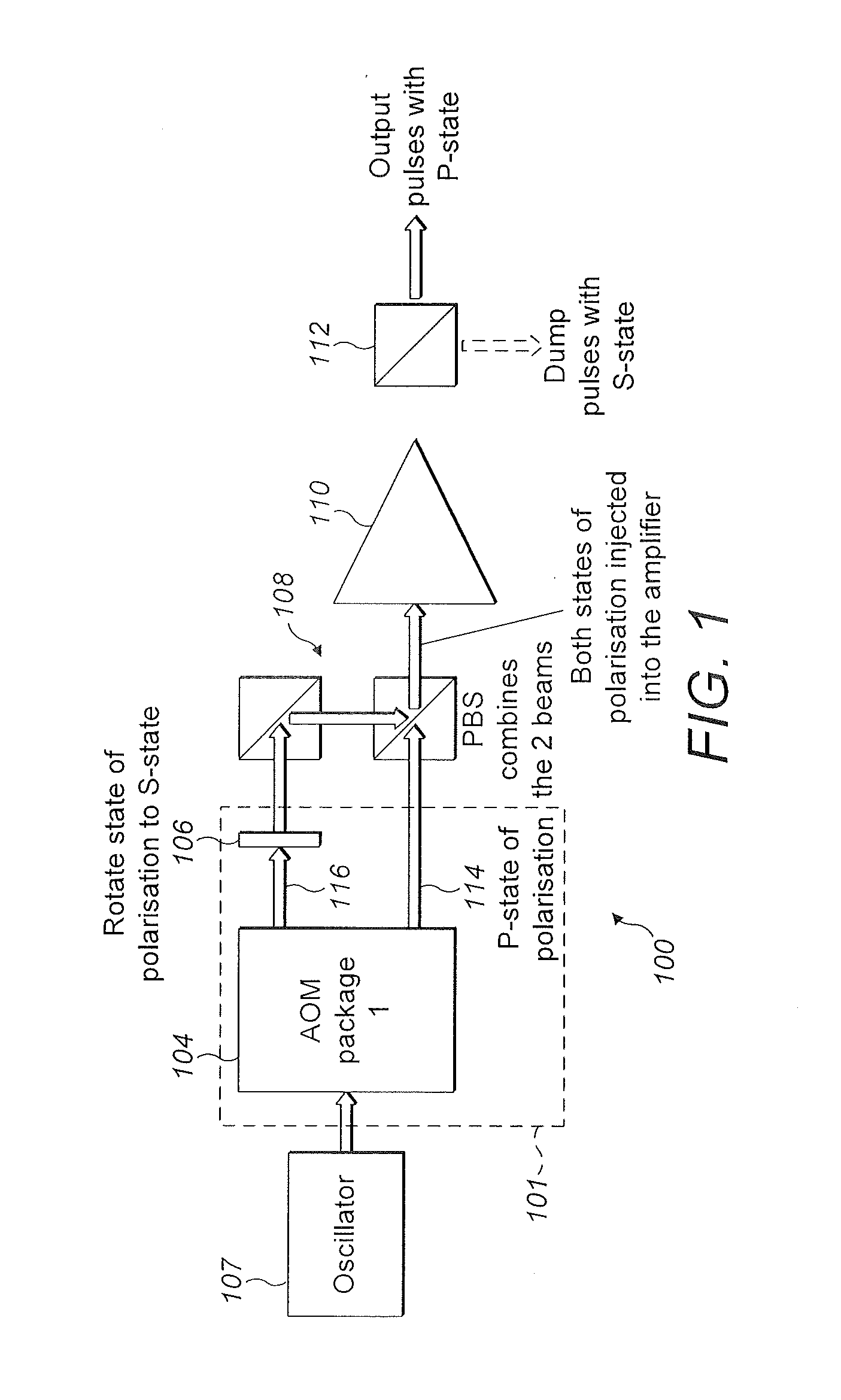
[0182]A second system design, also based on the use of polarisation and modulation, is shown in FIG. 6. The system of FIG. 6 is substantially the same as the system of FIG. 1, apart from the following modifications. The same reference numerals are retained for corresponding features.

[0183]This optical apparatus 101 of the system 600 of FIG. 6 includes two modulators 104a, 104b rather than one, with the zero order output of the first modulator 104a used as the input to the second modulator 104b.

[0184]The diffracted order output beam 602 from the first modulator 104a propagates with one state of polarisation and the diffracted order output beam 604 from the second modulator 104b passes through a polarisation rotator (phase plate) 106 such that the beam has an substantially orthogonal state of polarisation to the first modulator diffracted beam 602.

[0185]This system can be operated in a number of ways. It can operate as the same as the previously described system, can be operated (e.g...

example 3

[0189]The same approach can be used to achieve, not only pulse selection but fast pulse amplitude control and hence the ability to modify the pulse energy of each individual pulse following amplification. FIG. 9 shows an example of how this can be achieved with the aid of pulse timing diagrams.

[0190]One can achieve this performance using the two modulator example of FIG. 6 and by having both amplitude and digital control of each of the modulators. For AOMs amplitude control involves adjustment of the diffraction efficiency of light into the diffracted order. This is achieved by controlling the magnitude of the RF amplifier power which controls the size of the acoustic field within the AOM crystal. AOM amplitude control is well known per se to those skilled in the art.

[0191]For EOM devices, amplitude control involves changing the magnitude of the applied voltage to the crystal.

[0192]Referring to FIG. 6, maximum output pulse energy following amplification and polarisation can be achie...

example 4

[0196]FIG. 10 shows a non-limiting example of how the system may be implemented in an all-optical fiber approach, for example within a modelocked fiber laser MOPA system. The optical system 1000 of FIG. 10 is substantially the same as the system of FIG. 6, apart from the following modifications. The same reference signs are used for corresponding features.

[0197]In the example of FIG. 10, the modulators 104a, 104b comprise AOMs and are fiber coupled. The second modulator 104b comprises a standard single output, diffracted order AOM. The first modulator is customised to have both the diffracted and the zero order delivered through polarization-maintaining (PM) optical fiber 1002.

[0198]Instead of a phase plate 106, the optical apparatus 101 comprises a 90 degree splice 1004 between the polarization-maintaining optical fiber 1002 at the output of the second modulator and a second piece of PM fiber 1006. In this way, the state of polarisation from the second AOM can be rotated through 90...


PUM


Abstract

An optical system comprises an optical apparatus arranged to direct received light to different paths and to provide a first signal and a second signal, said first and second signals having an optical difference therebetween sufficient for distinguishing optical signals, an amplifier in optical communication with the optical apparatus for amplifying the first and second signals, and a discrimination device to receive amplified light and to provide output light responsive to the optical difference.

Description

FIELD OF THE INVENTION[0001]This invention relates to optical systems, such as, for example, laser systems based around a MOPA (Master Oscillator Power Amplifier) architecture wherein the output of a lower power source (e.g., a diode, mode locked laser or other oscillator) is amplified with an amplifier to a higher power. In particular, but not exclusively, it relates to laser MOPA systems incorporating signal discrimination based modulation and external switching.BACKGROUND TO THE INVENTION[0002]Modulation of the laser beam is desirable in many laser systems. In ultrafast lasers, it is often of interest to have an ability to select individual pulses, burst of pulses, to reduce the pulse repetition rate and to switch on and off the laser beam with extremely short rise and fall times. It can also be desirable to modify the amplitude of a pulse to a selected non-zero value, or to otherwise affect a signal. In CW lasers, it can be of interest to gate the output, for example to turn on ...

Claims


Application Information

Patent Timeline
IPC IPC(8): G02F1/365
CPCG02F1/365G02F1/113G02F1/353G02F2201/02H01S3/005H01S3/0085H01S3/0092H01S3/10015H01S3/10061H01S3/1302H01S3/2308H01S3/2391
Inventor CLOWES, JOHN REDVERSCODEMARD, CHRISTOPHEDUPRIEZ, PASCAL
Owner NKT PHOTONICS
Why Eureka
Try Eureka