

Cavitation-resistant environmental barrier coatings
a technology of cavitation resistance and environmental barrier, which is applied in the direction of superimposed coating process, machines/engines, mechanical equipment, etc., can solve the problems of reducing the cavitation resistance of the ebc system, debonding and spallation of the coating, and not adhesion well of the si-containing material (sic or silicon), so as to improve the delamination resistance and cavitation resistance
- Summary
- Abstract
- Description
- Claims
- Application Information
AI Technical Summary
Benefits of technology
Problems solved by technology
Method used
Image

Examples
Embodiment Construction
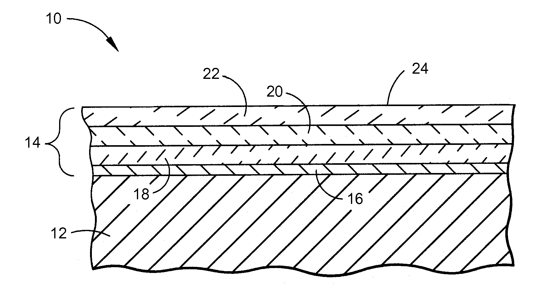
[0015]Embodiments described herein generally relate to environmental barrier coating (EBC) systems for high temperature ceramic components.
[0016]The EBC systems described herein may be suitable for use in conjunction with CMCs or monolithic ceramics. As used herein, “CMC” refers to silicon-containing matrix and reinforcing materials. Some examples of CMC systems acceptable for use herein can include, but should not be limited to, materials having a matrix and reinforcing fibers comprising silicon carbide, silicon nitride, and mixtures thereof. As used herein, “monolithic ceramics” refers to materials comprising silicon carbide, silicon nitride, and mixtures thereof. CMC systems and monolithic ceramics are collectively referred to herein as “ceramics.”
[0017]The EBC systems herein may be suitable for application to “ceramic components,” or simply “components,” found in high temperature environments (e.g. operating temperatures of about 2500° C.), such as those present in turbomachiner...
PUM
| Property | Measurement | Unit |
|---|---|---|
| operating temperatures | aaaaa | aaaaa |
| weight percent | aaaaa | aaaaa |
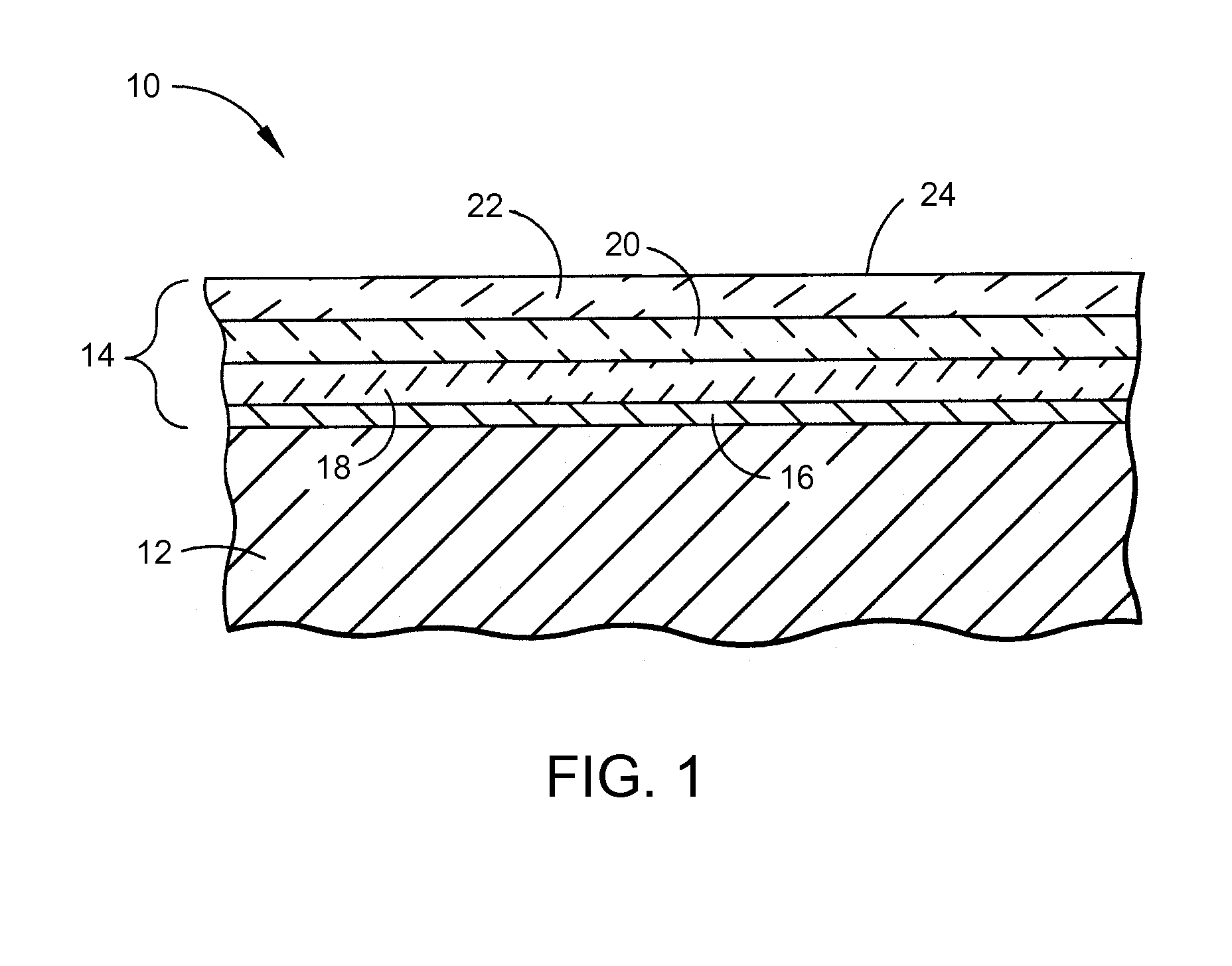
| grain boundaries | aaaaa | aaaaa |
Abstract
Description
Claims
Application Information