
Adaptive DC-link voltage controlled LC coupling hybrid active power filters for reactive power compensation

a technology of reactive power compensation and active power filter, which is applied in the direction of electric variable regulation, process and machine control, instruments, etc., can solve the problems of resonance problems, low dynamic performance, and low initial and operational cost, and achieve the effect of reducing switching loss and switching nois

Active Publication Date: 2014-02-27
UNIVERSITY OF MACAU
View PDF2 Cites 9 Cited by
  • Summary
  • Abstract
  • Description
  • Claims
  • Application Information

AI Technical Summary

Benefits of technology

The present invention provides an adaptive dc-link voltage control algorithm for LC-HAPF reactive power compensation. This algorithm reduces switching loss and switching noise, and decreases operational cost. Additionally, the invention includes a PWM circuit to generate PWM trigger signals to drive switching elements of the voltage source inverter for LC-HAPF adaptive dc-link voltage control and dynamic reactive power compensation, which further reduces switching noise and improves operational efficiency.

Problems solved by technology

Unfortunately, they have many disadvantages such as low dynamic performance, resonance problems, and filtering characteristic that is easily affected by small variations of the system parameters.
APFs can overcome the disadvantages inherent in PPFs, but their initial and operational costs are relatively high because the dc-link operating voltage should be higher than the system voltage.
This results in slowing down their large-scale application in distribution networks.
The HAPF topologies consist of many passive components, such as transformers, capacitors, reactors, and resistors, thus increasing the size and cost of the whole system.
In practical, because the load-side reactive power consumption varies from time to time, the LC-HAPF cannot perform satisfactory dynamic reactive power compensation.
The larger the reactive power compensation difference between the load-side and coupling LC, the larger the system current and loss, and it will lower the power network stability.
In addition, if the loading is dominated by a centralized air-conditioning system, its reactive power consumption will be much higher than the harmonic power consumption.
Since the switching loss is directly proportional to the dc-link voltage, the system will obtain a larger switching loss if a higher dc-link voltage is used, and vice versa.

Method used


Image

  • Adaptive DC-link voltage controlled LC coupling hybrid active power filters for reactive power compensation
  • Adaptive DC-link voltage controlled LC coupling hybrid active power filters for reactive power compensation
  • Adaptive DC-link voltage controlled LC coupling hybrid active power filters for reactive power compensation

Examples


Embodiment Construction

[0026]A preferred embodiment of the present invention will be described hereinafter with reference to the accompany drawings.

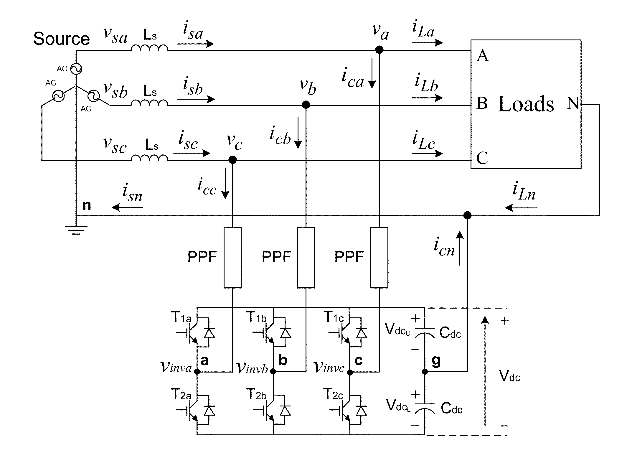
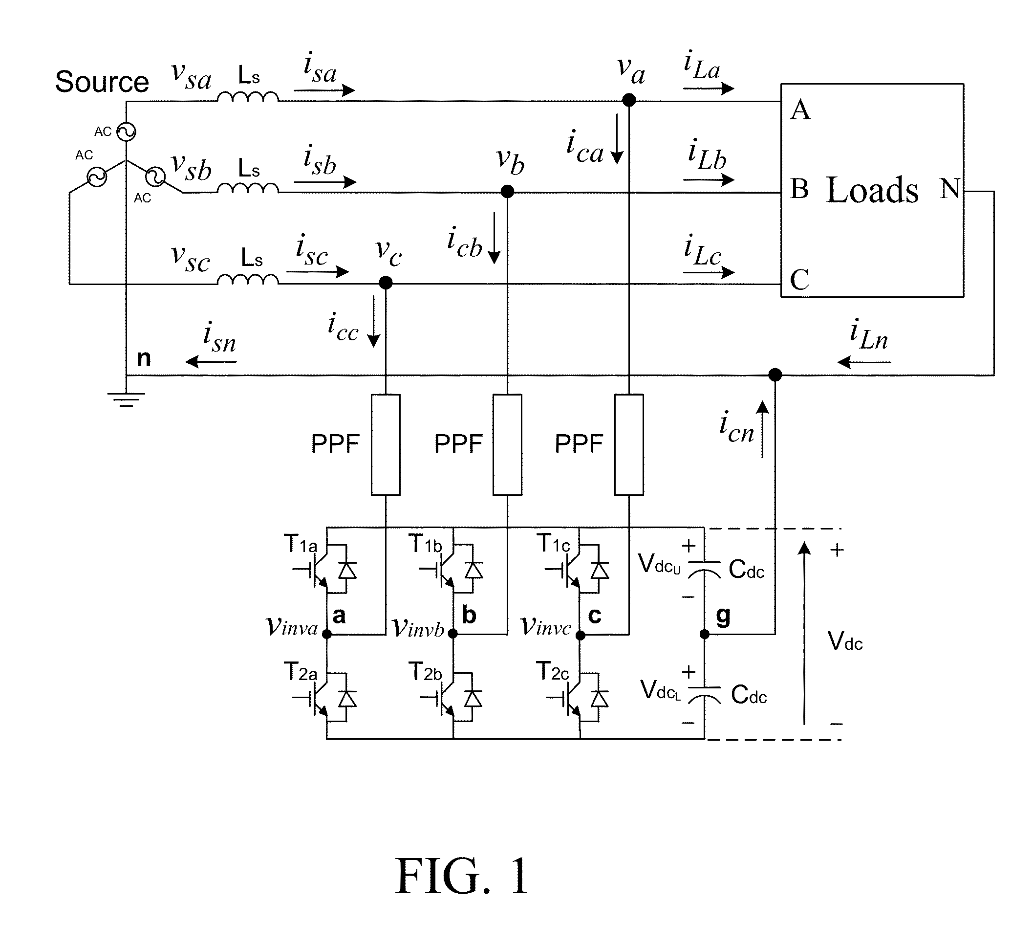
[0027]Reference is now made to FIG. 1. A transformerless two-level three-phase four-wire center-split current quality compensator (CCQC) is shown in FIG. 1, where the subscript ‘x’ denotes phase a,b,c,n. v is the system voltage, vx is the load voltage. Ls is the system inductance normally neglected due to its low value relatively, thus vsx≈vx. isx, iLx and icx are the system, load and inverter current for each phase. PPF is the coupling passive power filter part, which can be composed of a resistor, inductor, capacitor or any combinations of them. Cdc, VdcU and VdcL are the dc capacitance, upper and lower dc capacitor voltages with VdcU=VdcL=0.5Vdc. The dc-link midpoint is assumed to be ground reference (g). From FIG. 1, the inverter line-to-ground voltages vinvx-g will be equal to the inverter line-to-neutral voltages vinvx-n because the neutral point n is co...


PUM


Abstract

An adaptive dc-link voltage controlled LC coupling hybrid active power filter (LC-HAPF) for reactive power compensation includes: two dc capacitors to provide dc-link voltage; a three-phase voltage source inverter to convert dc-link voltage into compensating voltages; three coupling LC circuits to convert compensating voltages into currents; and an adaptive dc voltage controller with reactive power compensation control algorithm. The control algorithm includes: first, calculating required minimum dc-link voltage in each phase with respect to loading reactive power; three-phase required minimum dc-link voltage will be maximum one among their minimum values; compare it with predetermined voltage levels to determine final reference dc-link voltage. A dc-link voltage feedback P / PI controller outputs dc voltage reference compensating currents. An instantaneous power compensation controller outputs reactive reference compensating currents. The final reference compensating currents will be sum of them. A PWM circuit provides LC-HAPF adaptive dc-link voltage control and dynamic reactive power compensation.

Description

TECHNICAL FIELD[0001]The present invention relates to a current quality compensator, and more particularly to an adaptive dc-link voltage controlled LC coupling hybrid active power filter for dynamic reactive power compensation under inductive loads.BACKGROUND ART[0002]Since the first installation of passive power filters (PPFs) in the mid 1940's, PPFs have been widely used to suppress current harmonics and compensate reactive power in distribution power systems due to their low cost, simplicity and high efficiency characteristics. Unfortunately, they have many disadvantages such as low dynamic performance, resonance problems, and filtering characteristic that is easily affected by small variations of the system parameters. Since the concept “Active ac Power Filter” was first developed by L. Gyugyi in 1976, the research studies of the active power filters (APFs) for current quality compensation are getting more interest since then. APFs can overcome the disadvantages inherent in PPF...

Claims


Application Information

Patent Timeline
IPC IPC(8): G05F1/70
CPCG05F1/70
Inventor LAM, CHI-SENGWONG, MAN-CHUNGCHOI, WAI-HEIHAN, YING-DUO
Owner UNIVERSITY OF MACAU
Learn More