
Ionic gel electrolyte, energy storage devices, and methods of manufacture thereof

a technology of liquid gel electrolyte and energy storage device, which is applied in the field of electrochemical cells, can solve the problems of low storage capacity and power capability of lithium-ion batteries, stringent requirements for hermetic encapsulation, and complex cell geometry and manufacturing

Active Publication Date: 2014-03-06
CCL LABEL INC +1
View PDF4 Cites 45 Cited by
  • Summary
  • Abstract
  • Description
  • Claims
  • Application Information

AI Technical Summary

Benefits of technology

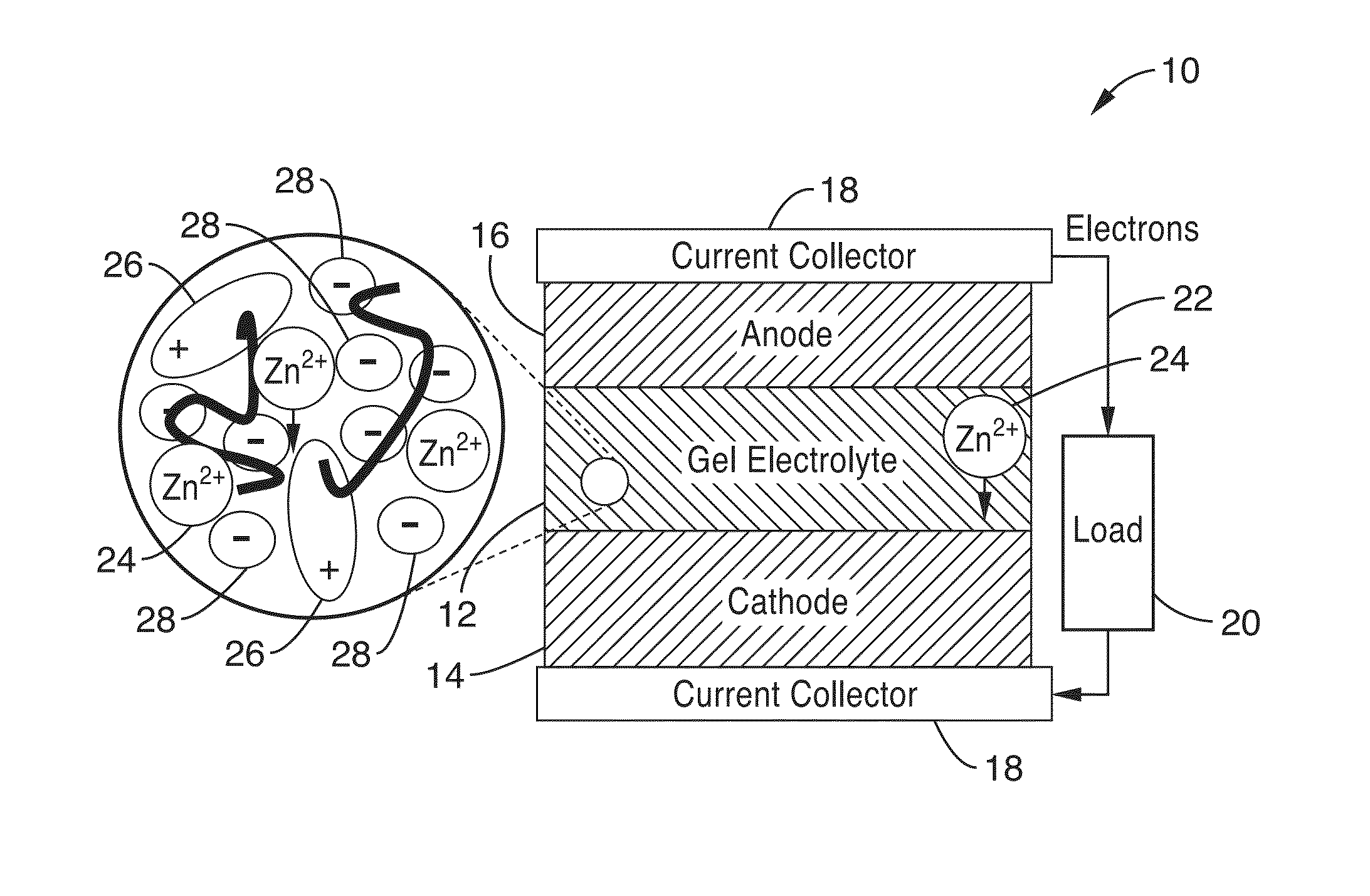
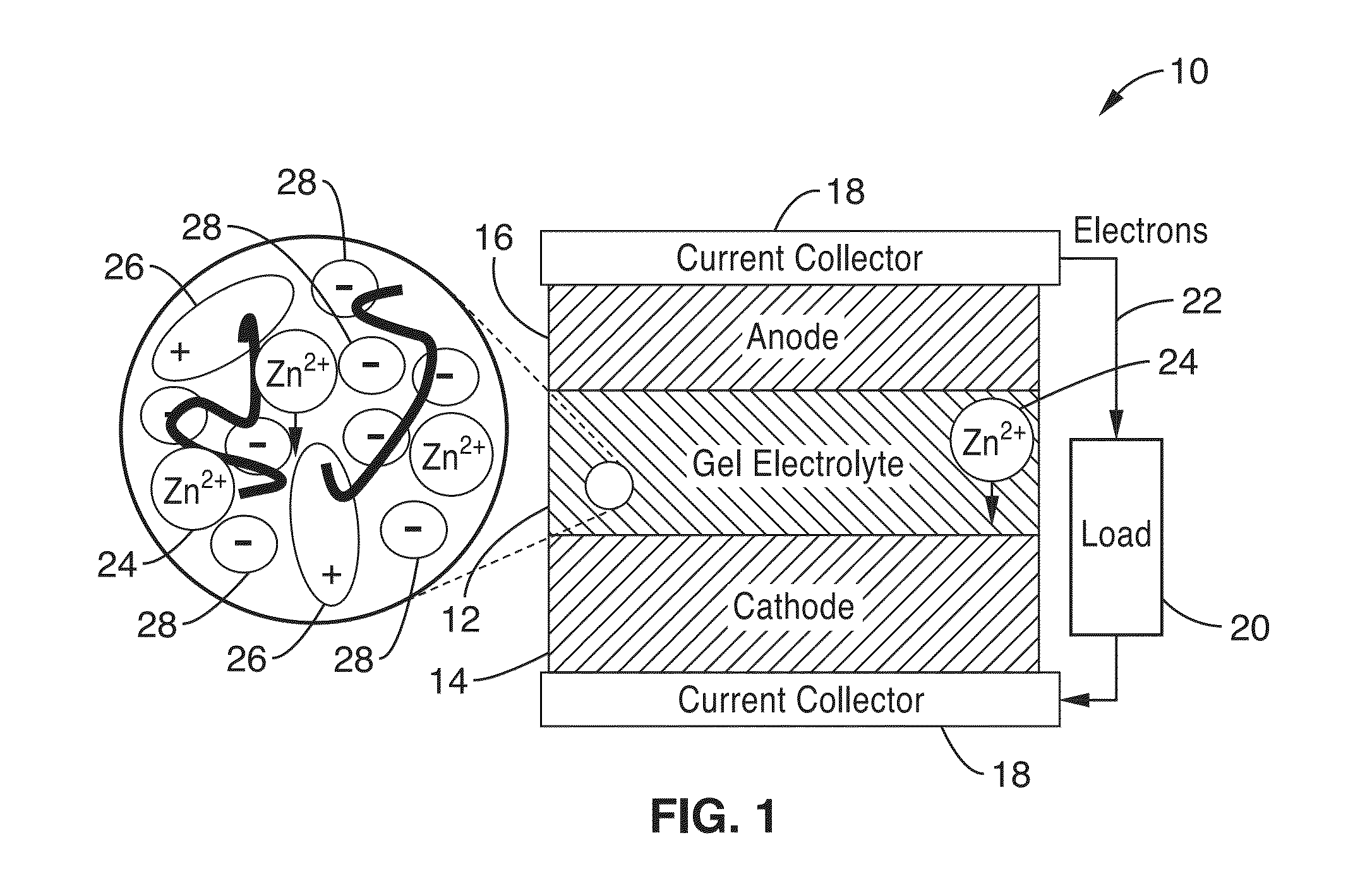
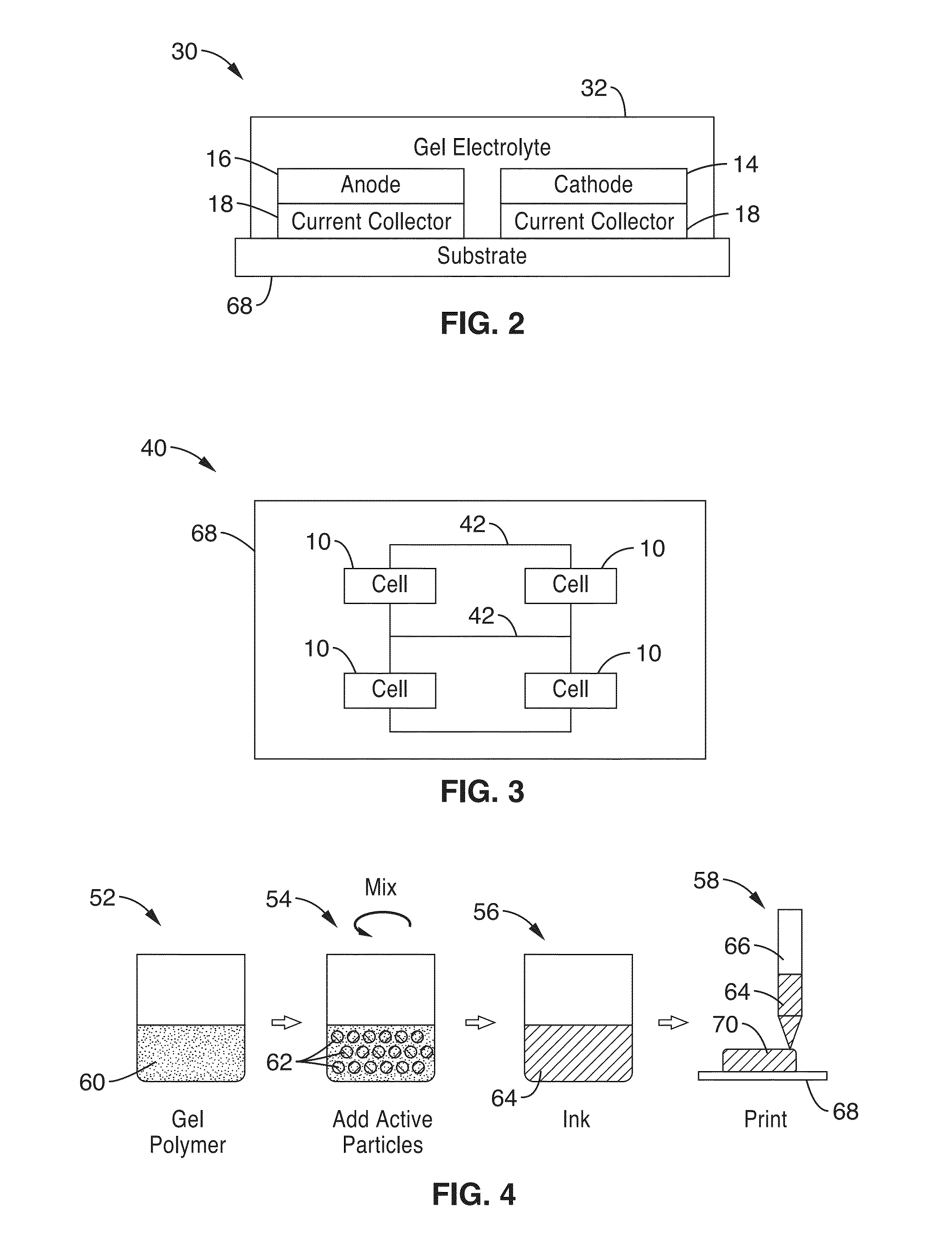
This patent describes a new type of electrochemical cell that uses a non-aqueous gel electrolyte with a polymer that has been soaked in ionic liquid and salt to create a stable barrier between the positive and negative electrodes. This electrolyte allows for the movement of multivalent ions between the two electrodes, resulting in a highly efficient and reliable battery. The patent also describes a method for fabricating these cells by printing layers of electrode ink and electrolyte ink, with the electrolyte ink providing separation between the electrodes. The technical effects of this patent include increased efficiency and reliability of electrochemical cells.

Problems solved by technology

Vapor deposited thin film lithium and lithium-ion batteries have low storage capacities and power capabilities due to materials deposition limitations.
Lithium polymer batteries have leveraged the rapid advancements of pouch cell battery manufacturing, but like thin film lithium and lithium-ion batteries, are plagued by stringent hermetic encapsulation requirements due to its sensitivity to contamination from the environment.
Semi-printed batteries often utilize a liquid electrolyte, adding cell geometry and manufacturing complexities.
Although microbattery chemistries may be similar to macrobattery chemistries, macrobattery configurations, packaging, and post-processing are not feasible below the centimeter scale.
Nickel-zinc systems have the problem that zinc dendrites grow, and the shape of the electrode changes during cycling, thus reducing cycle life.
Lithium-ion and lithium polymer systems require strict charge and discharge regulation and pose flammability risks.

Method used


Image

  • Ionic gel electrolyte, energy storage devices, and methods of manufacture thereof
  • Ionic gel electrolyte, energy storage devices, and methods of manufacture thereof
  • Ionic gel electrolyte, energy storage devices, and methods of manufacture thereof

Examples


embodiment 1

[0213]2. An electrochemical cell as recited in embodiment 1, wherein the anode layer, cathode layer, and electrolyte layer comprise flexible, compressible layers capable of deformation without significant loss of performance.

embodiment 2

[0214]3. An electrochemical cell as recited in embodiment 2, wherein the cell comprises a battery cell.

embodiment 3

[0215]4. An electrochemical cell as recited in embodiment 3, wherein the battery cell is a rechargeable battery cell.

[0216]5. An electrochemical cell as recited in embodiment 1, further comprising: a first current collector in electronic communication with the cathode; and a second current collector in electronic communication with the anode.

[0217]6. An electrochemical cell as recited in embodiment 1, wherein one or more of the anode layer, cathode layer, electrolyte layer and current collectors are configured to be deposited an a substrate in a liquid form, and solidify to at least a semi-solid state after a period of time.

[0218]7. An electrochemical cell as recited in embodiment 1, wherein the cell is configured to operate in an ambient environment for over 4 months with no additional packaging.

[0219]8. An electrochemical cell as recited in embodiment 1, wherein the polymer network comprises one or more polymer(s) selected from the group consisting of poly(vinylidene fluoride) (PV...


PUM

PropertyMeasurementUnit
thicknessaaaaaaaaaa
thicknessaaaaaaaaaa
melting pointsaaaaaaaaaa

Abstract

An electrochemical cell includes solid-state, printable anode layer, cathode layer and non-aqueous gel electrolyte layer coupled to the anode layer and cathode layer. The electrolyte layer provides physical separation between the anode layer and the cathode layer, and comprises a composition configured to provide ionic communication between the anode layer and cathode layer by facilitating transmission of multivalent ions between the anode layer and the cathode layer.

Description

CROSS-REFERENCE TO RELATED APPLICATIONS[0001]This application is a continuation of U.S. patent application Ser. No. 13 / 784,935 filed on Mar. 5, 2013, incorporated herein by reference in its entirety, which is a 35 U.S.C. §111(a) continuation of PCT international application number PCT / US2011 / 051469 filed on Sep. 13, 2011, incorporated herein by reference in its entirety, which is a nonprovisional of U.S. provisional patent application Ser. No. 61 / 382,027 filed on Sep. 13, 2010, incorporated herein by reference in its entirety. Priority is claimed to each of the foregoing applications.[0002]The above-referenced PCT international application was published as PCT International Publication No. WO 2012 / 037171 on Mar. 22, 2012 and republished on Aug. 2, 2012, and said publications are incorporated herein by reference in their entirety.STATEMENT REGARDING FEDERALLY SPONSORED RESEARCH OR DEVELOPMENT[0003]Not ApplicableINCORPORATION-BY-REFERENCE OF MATERIAL SUBMITTED ON A COMPACT DISC[0004]N...

Claims


Application Information

Patent Timeline
Patent Type & Authority Applications(United States)
IPC IPC(8): H01G9/00H01G9/145H01M10/0565H01M10/058
CPCH01G9/0029H01M10/058H01G9/145H01M10/0565H01B1/122H01M2300/0045H01M2300/0085H01M10/0436H01M10/054H01G11/56Y10T29/49108Y10T29/49115H01M6/40Y02E60/10Y02P70/50H01B1/06H01G9/035H01M4/64H01M6/16H01M10/05Y02E60/13H01G9/0032H01G9/028H01G9/042H01G9/15H01G11/46H01G11/86H01M4/38H01M4/381H01M4/483H01M4/502H01M4/523H01M4/56H01M4/661H01M4/669H01M2220/30
Inventor WRIGHT, PAUL K.EVANS, JAMES W.HO, CHRISTINE
Owner CCL LABEL INC
Learn More