

Polarizing element, projector and method of manufacturing polarizing element
a technology of polarizing elements and projectors, applied in the field of polarizing elements, can solve the problems of insufficient mechanical strength of devices, limitation of enhancement properties, and high deformation, and achieve the effects of suppressing thermal degradation, improving heat-resistance properties of polarizing plates, and achieving desirable extinction ratios
- Summary
- Abstract
- Description
- Claims
- Application Information
AI Technical Summary
Benefits of technology
Problems solved by technology
Method used
Image

Examples
Embodiment Construction
[0048]A polarizing element, a projector and a method of manufacturing a polarizing element according to the present invention will now be more particularly described with reference to the accompanying drawings according to the following order. It should be noted that the present invention is not limited to the embodiments described below and various modifications can be added to the embodiment without departing from the scope of the present invention. The features shown in the drawings are illustrated schematically and are not intended to be drawn to scale. Actual dimensions should be determined in consideration of the following description. Moreover, dimensional relations and proportions may be different among the drawings in some parts.
1. Constitution of a Polarizing Element
2. Evaluation Test of Optical Property
3. Manufacturing Method of a Polarizing Element
4. Exemplary Constitution of a Liquid Crystal Projector
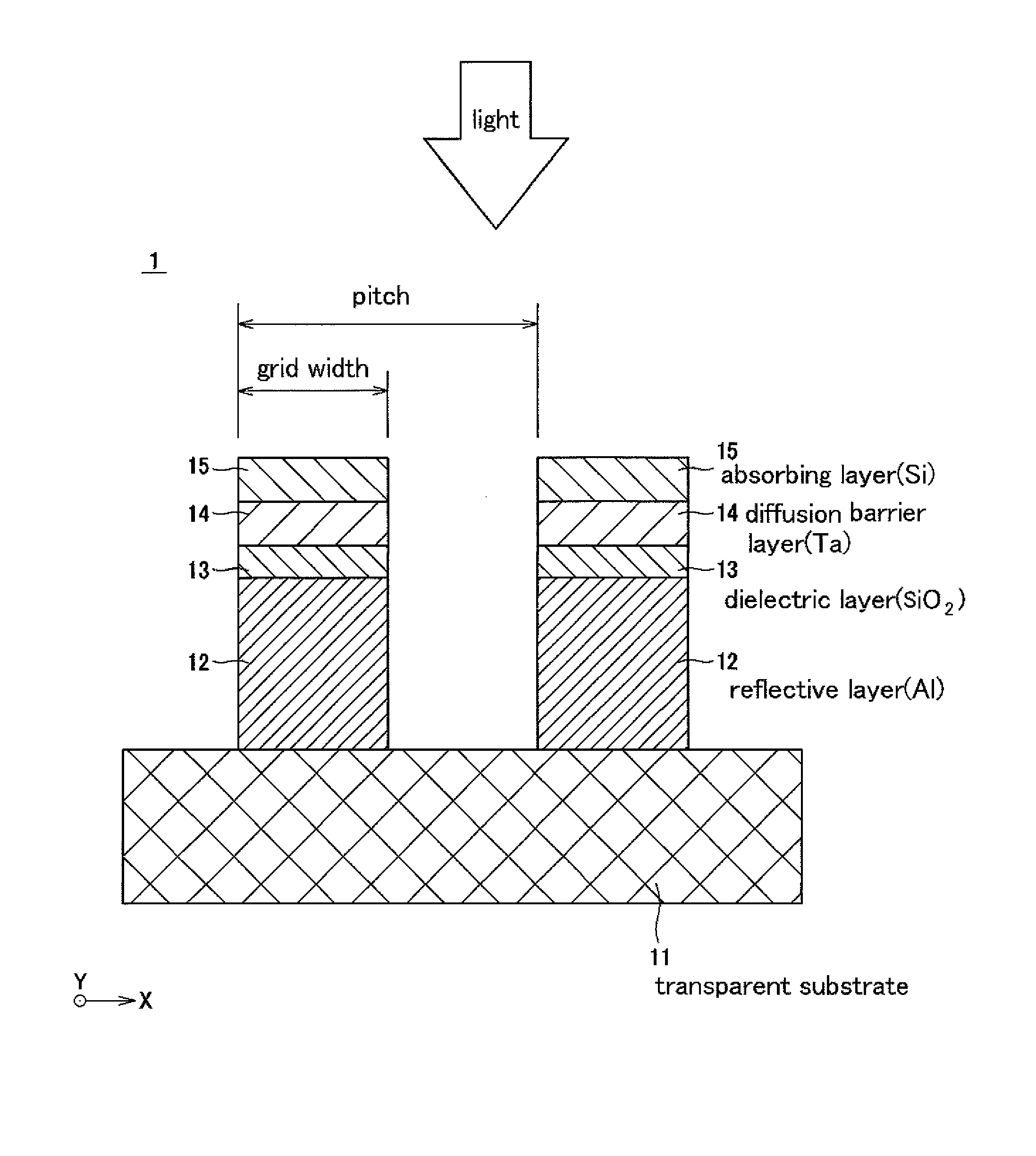
1. Constitution of a Polarizing Element
[0049]FIG. 1 is a schematic cro...
PUM
 Abstract
Description
Claims
Application Information