Optical neuron stimulation prosthetic using silicon carbide

a technology of optical neuron stimulation and silicon carbide, which is applied in the direction of manufacturing tools, surgery, therapy, etc., can solve the problems of degrading neural prosthetics in-vivo, unable to meet the needs of patients,

Inactive Publication Date: 2014-03-06
UNIV OF SOUTH FLORIDA
View PDF7 Cites 18 Cited by
  • Summary
  • Abstract
  • Description
  • Claims
  • Application Information

AI Technical Summary

Benefits of technology

[0013]Yet another embodiment of this device uses light emitters directly fabricated at points along the length of the prosthetic (FIG. 2). This configuration eliminates the need to guide light down the length of the prosthetic using waveguides but requires conductive traces to power each light emitting diode (LED) structure to run along the length of the device. Commonly, optical stimulation prosthetics with integrated LEDs are made using cytotoxic semiconductors such as GaAs. Often, these materials are coated in biocompatible polymers such as polyimide, but this leads to device fail

Problems solved by technology

Currently, these devices are extremely lifetime limited.
This immunologic response, coupled with the chemically harsh environment of the body, quickly degrades neural prosthetics in-vivo.
Beginning from the moment of implantation, performance begins to degrade and eventually terminates in total failure.
To complicate the issue, electrically active prosthetics such as wireless and optoelectronic devices use these materials as a protective coating to encapsulate otherwise poisonous electronic components.
First, the materials reduce the amount of immunologic response caused by the prosthesis.
Second, these materials provide a barrier between the body and the prosthetic in an attempt to save the body from undue exposure to otherwise toxic substances.
In the case o

Method used


Image

  • Optical neuron stimulation prosthetic using silicon carbide
  • Optical neuron stimulation prosthetic using silicon carbide
  • Optical neuron stimulation prosthetic using silicon carbide

Examples


Embodiment Construction

[0026]In the following detailed description of preferred embodiments, reference is made to the accompanying drawings, which form a part hereof, and within which are shown by way of illustration specific embodiments by which the invention may be practiced. It is to be understood that other embodiments may be utilized and structural changes may be made without departing from the scope of the invention.

[0027]As used herein, the term “dura” refers to the fibrous covering over the brain and inside the skull.

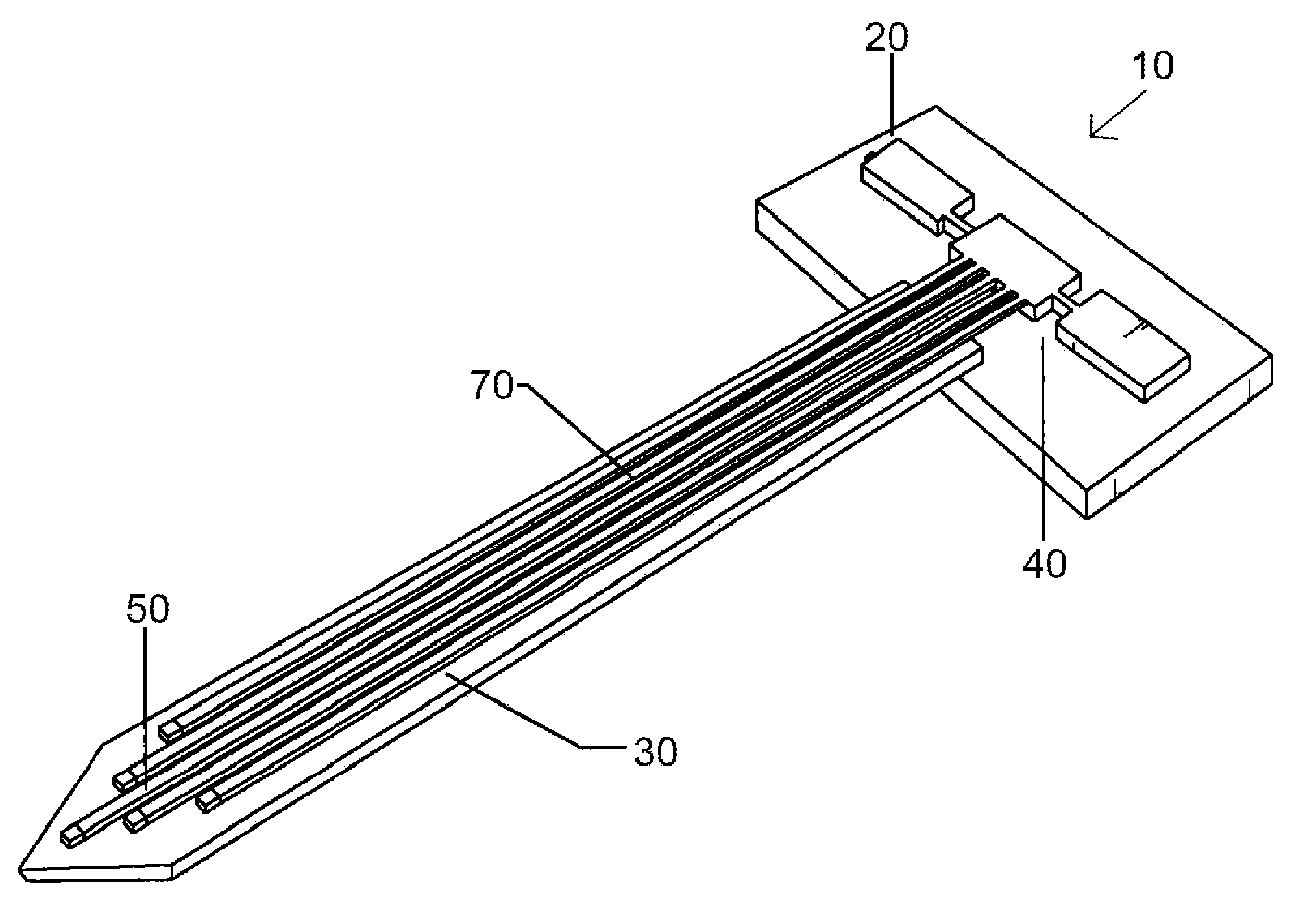
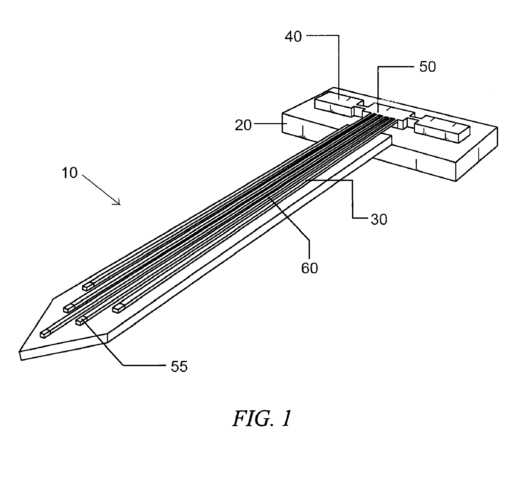
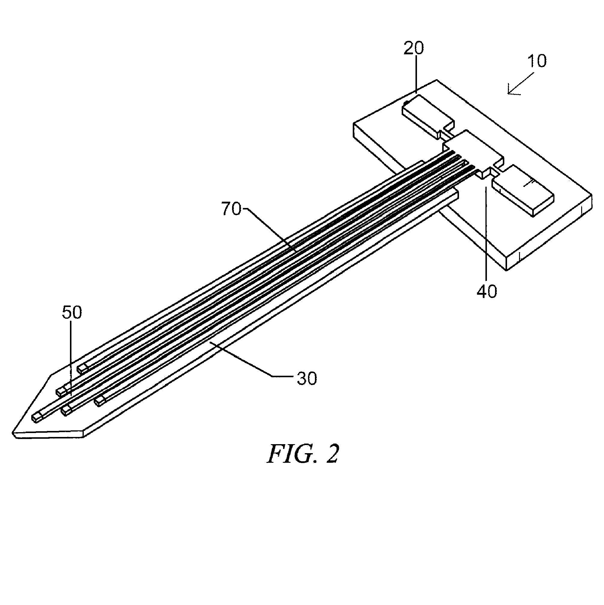
[0028]As used herein, the term “shank” refers to the long thin SiC structure on the device that pierces the dura and makes intimate contact with the neural tissue.

[0029]As used herein, the term “support” refers to the top region of the prosthetic that remains outside the dura and contains the majority of the prosthetic's electrical subsystems.

[0030]As used herein, the term “ASIC” refers to an Application Specific Integrated Circuit. ASIC is the general purpose processer used on the de...


PUM

PropertyMeasurementUnit
Action potentialaaaaaaaaaa
Flexibilityaaaaaaaaaa
Transparencyaaaaaaaaaa

Abstract

The microfabricated prosthetic device uses local, direct, and wavelength-specific optical stimulation to achieve an action potential from a single or small group of neurons within the central nervous system (CNS). The device is biocompatible, mechanically flexible, and optically transparent. The device can also use integrated electrodes for additional input/output (IO) locations, signal verification, feedback, wireless communication, and characterization of the electrochemically-evoked potential received from the activated neuron. The purpose of the device is to act as a neural interface prosthetic. The prosthetic is designed as the central component of a brain machine interface (BMI).

Description

CROSS REFERENCE TO RELATED APPLICATIONS[0001]This application is a continuation of prior filed International Application, Serial Number PCT / US2012 / 023131, filed Jan. 30, 2012, entitled “Optical Neuron Stimulation Prosthetic Using SiC (Silicon Carbide)” which claims priority to U.S. Provisional Patent Application No. 61 / 437,346 filed Jan. 28, 2011, entitled “Optical Neuron Stimulation Prosthetic Using SiC (Silicon Carbide)”. The content of each of which is incorporated herein by reference.FIELD OF THE INVENTION[0002]This invention relates to a device and method for optical neuron stimulation prosthetics using silicon carbide (SiC).BACKGROUND OF INVENTION[0003]The importance of controlling action potentials in certain cell types was emphasized first by Francis Crick in his Kuffler Lectures at the University of California in San Diego 2002. Soon after this talk, an explosion of genetic targeting experiments culminated in the Deisseroth group genetically isolating a photosensitive ion c...

Claims


Application Information

Patent Timeline
IPC IPC(8): A61N5/06
CPCA61L31/02A61L2400/18A61N5/0622A61N2005/0612A61L2430/32A61N2005/0651Y10T29/49826
Inventor REGISTER, JOSEPH J.SADDOW, STEPHEN E.FREWIN, CHRISTOPHER L.WEEBER, EDWIN
Owner UNIV OF SOUTH FLORIDA
Why Eureka
Try Eureka