Catalysts for the reduction of ammonia emission from rich-burn exhaust

a technology of ammonia emission and catalyst, which is applied in the direction of physical/chemical process catalyst, machine/engine, separation process, etc., can solve the problems of system exceeding nosub>x /sub>regulation, nh/sub>emission generation, etc., and achieve the effect of reducing ammonia (nh3) emission and high selectivity to n2

Active Publication Date: 2014-03-20
JOHNSON MATTHEY PLC
View PDF4 Cites 11 Cited by
  • Summary
  • Abstract
  • Description
  • Claims
  • Application Information

AI Technical Summary

Benefits of technology

[0006]According to an embodiment of the invention, a small pore molecular sieve catalyst is used as an ammonia oxidation catalyst (AOC) for rich-burn engine applications operating at high temperatures. We have found that catalysts comprising a small pore molecular sieve supporting at least one transition metal may be used in such applications for NH3 oxidation with very high selectivity to N2. Similar catalysts have previously been employed in lean burn applications for selective catalytic reduction (SCR) of NOx with NH3. It is atypical, however, to utilize such catalysts as oxidation catalysts to oxidize NH3 to form N2 and H2O. The inventors of the present invention, however, have found that NH3 oxidation catalysts (AOC) including a small pore molecular sieve supporting at least one transition metal can be favorably employed, including in rich-burn engines operating at high temperatures or to treat other exhaust gases susceptible to allowing an undesirable amount of NH3 slip. Novel systems and methods which employ such catalysts are provided herein.
[0007]According to one embodiment of the present invention, a system for reducing ammonia (NH3) emissions comprises: (a) a first component comprising a first substrate and a three-way catalyst disposed thereon, wherein the first component is disposed upstream of, and in fluid communication with, a second component comprising a second substrate and an ammonia oxidation catalyst disposed thereon, wherein said ammonia oxidation catalyst comprises a small pore molecular sieve supporting at least one transition metal; and (b) an oxygen-containing gas input disposed between said first and second components.
[0008]In a further embodiment of the present invention, the system additionally includes: (c) a first gaseous feed stream comprising exhaust gas derived from a rich-burn combustion process, wherein said feed stream is upstream of, and in fluid communication with, the first component; and (d) a conduit disposed between, and in fluid communication with, the first and second components and in fluid communication with said oxygen-containing gas input. In at least one embodiment, the small pore molecular sieve for NH3 oxidation is a Cu-supported CHA Framework Type small pore molecular sieve, such as a Cu-supported SAPO-34.
[0009]In yet a further embodiment of the present invention, the AOC catalyst includes a small pore molecular sieve supporting a transition metal in the form of a first catalyst layer. In another embodiment, the AOC catalyst may include a second catalyst layer comprising a platinum group metal, wherein the first catalyst layer is disposed relative to the second catalyst layer such that the exhaust contacts the first catalyst layer before contacting the second catalyst layer. The platinum group metal may be, for example, ruthenium (Ru), rhodium (Rh), palladium (Pd), rhenium (Re), iridium (Ir) and platinum (Pt), and mixtures thereof. In

Problems solved by technology

Generally, the use of diesel engine catalysts for gasoline engines, stationary diesel or natural gas engines, results in the generation of NH3 emissions since the catalyst is very active.
The catalysts employed by these systems, however, fail to achieve high selectivity of NH3 to N2 at temperatures above 400° C., where excessive oxidation of NH3 to NOx can lead to the system exceeding NOx regulations.
Similar to the known two-staged systems, however, kn

Method used


Image

  • Catalysts for the reduction of ammonia emission from rich-burn exhaust
  • Catalysts for the reduction of ammonia emission from rich-burn exhaust
  • Catalysts for the reduction of ammonia emission from rich-burn exhaust

Examples


example 1

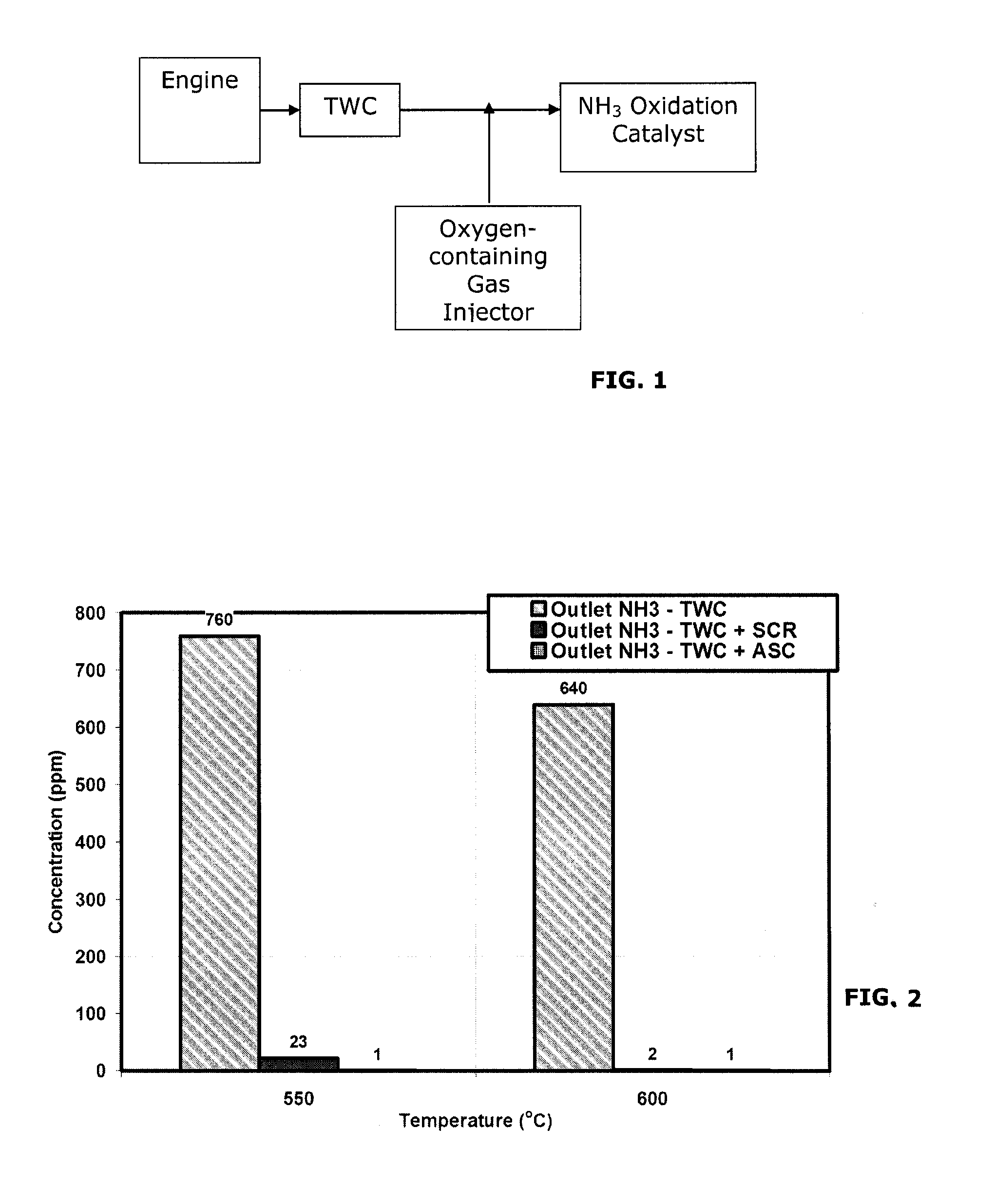
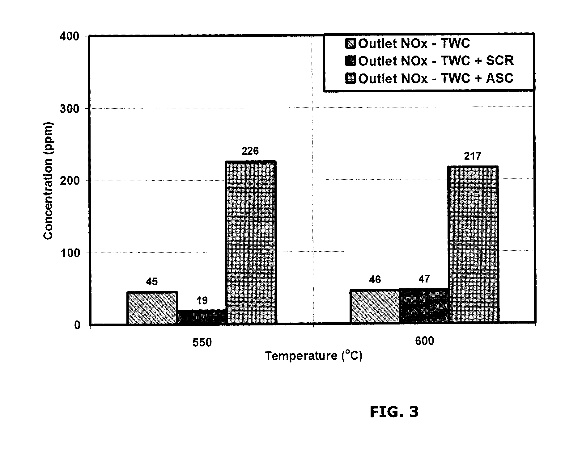
[0056]A test was performed to measure ammonia (NH3) emissions and nitrogen oxide (NOx) emissions from a comparative system and systems of the invention. A comparative system containing a three-way catalyst (TWC) was compared with a system including a three-way catalyst and an NH3 oxidation catalyst (TWC-AOC system), according to one embodiment of the present invention, and a system including a three-way catalyst and a multi-layer NH3 oxidation catalyst system containing an ammonia slip catalyst (TWC-ASC), according to another embodiment of the present invention. The multi-layer NH3 oxidation catalyst system included a first layer (i.e., top-layer) of a small pore molecular sieve supported transition metal catalyst and a second layer (under-layer) of a platinum group metal catalyst. Specifically, Cu / SAPO-34 was used as the top-layer and platinum was used as the under-layer of the multi-layer NH3 oxidation catalyst. In particular, the catalyst layers were coated along the walls of a f...

example 2

[0059]A test was performed to compare the effect of transition metal loading on the emission reduction capabilities of the small pore molecular sieve catalyst. Copper was employed as the transition metal. A comparative system containing a three-way catalyst (TWC) was compared with a system according to the invention including a three-way catalyst and NH3 oxidation catalyst (TWC-AOC system) having a 2.5% copper loading and a system according to the invention including a three-way catalyst and a three-way catalyst and NH3 oxidation catalyst (TWC-AOC system) having a 4.2% copper loading. Specifically, Cu / SAPO-34 is used as the NH3 oxidation catalyst.

[0060]The space velocity of the gas flow was 100,000 hr−1 at the TWC catalyst and 50,000 hr−1 at the NH3 oxidation catalyst. The exhaust gas at the inlet to the TWC catalyst comprised: 1410 ppm C3H8 as C1, 0.45% CO, 0.15% H2, 2700 ppm NO, 0.25% O2, 10% CO2, 10% H2O, with the balance comprising N2. The lambda value of the exhaust gas at the ...

example 3

[0062]A test was performed to compare the effect of temperature on emission reduction capabilities of the small pore molecular sieve catalyst. Copper was employed as the transition metal. A comparative system containing a three-way catalyst (TWC) was compared with a system according to the invention including a three-way catalyst and NH3 oxidation catalyst (TWC-AOC system) having a 4.2% copper loading. Specifically, Cu / SAPO-34 is used as the NH3 oxidation catalyst.

[0063]The space velocity of the gas flow was 100,000 hr—1 at the TWC catalyst and 50,000 hr−1 at the NH3 oxidation catalyst. The exhaust gas at the inlet to the TWC catalyst comprised: 1410 ppm C3H8 as C1, 0.45% CO, 0.15% H2, 2700 ppm NO, 0.25% O2, 10% CO2, 10% H2O, with the balance comprising N2. The lambda value of the exhaust gas at the TWC catalyst was calculated as 0.9905, while the lambda value of the gas at the NH3 oxidation catalyst, after the injection of the oxygen-containing gas, was calculated as about 1.022. 0...


PUM

PropertyMeasurementUnit
Temperatureaaaaaaaaaa
Weightaaaaaaaaaa
Ratioaaaaaaaaaa

Abstract

A system for reducing ammonia (NH3) emissions includes (a) a first component comprising a first substrate containing a three-way catalyst, wherein the first component is disposed upstream of a second component comprising a second substrate containing an ammonia oxidation catalyst, wherein said ammonia oxidation catalyst comprises a small pore molecular sieve supporting at least one transition metal; and (b) an oxygen-containing gas input disposed between the components. For example, a CHA Framework Type small pore molecular sieve may be used. A method for reducing NH3 emission includes introducing an oxygen-containing gas into a gas stream to produce an oxygenated gas stream; and exposing the oxygenated gas stream to an NH3 oxidation catalyst to selectively oxidize at least a portion of the NH3 to N2. The method may further include the step of exposing a rich burn exhaust gas to a three-way catalyst to produce the gas stream comprising NH3.

Description

FIELD OF THE INVENTION[0001]The present invention relates to small pore molecular sieve supported transition metal catalysts. The present invention further relates to systems which employ small pore molecular sieve supported transition metal catalysts for the reduction of ammonia (NH3) from rich-burn exhaust.BACKGROUND OF THE INVENTION[0002]Typical engine exhaust is a heterogeneous mixture which contains, among other constituents, gaseous emissions such as carbon monoxide (CO), unburned or partially burned hydrocarbons or oxygenates thereof (HC) and nitrogen oxides (NOx). Often, catalyst compositions and substrates on which the compositions are disposed are provided in engine exhaust systems to convert certain or all of these exhaust components to innocuous components. For example, three-way (TWC) catalysts are known to be suitably employed on stationary rich-burn engines to reduce the emissions of nitrogen oxides (NOx), hydrocarbons (HC), and carbon monoxide (CO). Because these eng...

Claims


Application Information

Patent Timeline
IPC IPC(8): B01J29/85F01N3/10B01D53/58
CPCB01J29/85F01N3/101B01D53/58B01D53/9436B01D53/945B01D53/9477B01D2255/1021B01D2255/20761B01D2255/50B01D2255/9022B01J29/072B01J29/076B01J29/763B01J37/0244B01J37/0246Y02T10/12
Inventor FEDEYKO, JOSEPH M.CHEN, HAI-YINGREINING, ARTHUR J.
Owner JOHNSON MATTHEY PLC
Why Eureka
Try Eureka