Unlock instant, AI-driven research and patent intelligence for your innovation.

Nanostructured silicide composites for thermoelectric applications

a technology of silicide composites and nanostructured silicides, applied in the direction of thermoelectric device junction materials, non-metal conductors, conductive materials, etc., can solve the problems of high cost, material problems to overcome, and low abundance of such devices

Active Publication Date: 2014-04-10
CALIFORNIA INST OF TECH
View PDF5 Cites 5 Cited by
  • Summary
  • Abstract
  • Description
  • Claims
  • Application Information

AI Technical Summary

Benefits of technology

This patent describes a method for making a material that can convert heat into electricity. The method involves heating a mixture of semiconductor material and metal complex to a high temperature, which forms small metal inclusions in the semiconductor material. These inclusions are evenly distributed throughout the material and make it a nanocomposite material. The resulting material has very good thermal conductivity and can be used to make thermoelectric devices. In another embodiment, the material has silicide inclusions that are even smaller than the metal inclusions, which further improve its performance.

Problems solved by technology

In order for thermoelectric devices to be used in large-scale applications, however, a number of materials problems must be overcome.
For instance, the materials used in such devices are typically associated with low abundance, high cost, high toxicity, low thermal stability, and / or poor oxidation resistance.
A problem with silicon-based thermoelectric materials, however, is that they generally have a thermal conductivity an order of magnitude too high to be an effective generator of thermoelectric power.
Although the resulting composite demonstrated a 40% reduction in the lattice thermal conductivity with an overall increase in figure of merit (ZT) of about 20%, the use of spark erosion to form such composites is impractical for large-scale applications.
In particular, spark erosion is too slow, costly, involves a complex set-up, and is low yielding.
However, such methods are limited by several factors in that commercially available nanoparticles are larger than the particle size required by thermoelectric models, unavailable for specific compositions and materials, and too costly.
Moreover, such nanoparticles are often functionalized or contaminated with oxide or thiolated capping agents which results in contamination of the resulting composite in addition to undesirable doping effects.
Other problems that arise from this approach include the agglomeration of nanoparticles into larger particles to minimize surface energy, and the settling of nanoparticles at grain boundaries as opposed to within the matrix as required by composite thermoelectric models.
Such characteristics in the final composite lead to undesirable thermoelectric transport properties.
In an approach to form such composites, Bux and co-workers used ball milling of Si0.80Ge0.20 and W (and Si and W) followed by hot pressing to form WSi2 inclusions in the Si matrix; however, due to the inclusions being too large and their size distribution too broad, the resulting composite did not demonstrate a significant reduction in lattice thermal conductivity (S. Bux et al., Materials Research Society, Symposium Proceedings, 2010, 1267, 1267-DD01-06).

Method used


Image

  • Nanostructured silicide composites for thermoelectric applications
  • Nanostructured silicide composites for thermoelectric applications
  • Nanostructured silicide composites for thermoelectric applications

Examples


example 1

Producing a Si / FeSi2 Nanocomposite Thermoelectric Material

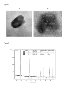
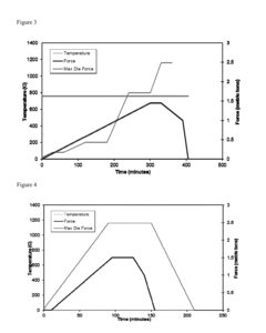
[0052]This example provides a method according to the present invention of producing a nanocomposite thermoelectric material comprising Si with FeSi2 inclusions.

[0053]A homogenous mixture of n-type Si powder and ferrocene was prepared by high-energy ball milling. The Si powder was prepared using a procedure previously reported by Bux and co-workers (S. Bux et al., Advanced Functional Materials, 2009, 19, 2445-2452). Approximately 50 mg of ferrocene (from Sigma Aldrich) was added to approximately 3 grams of Si powder to yield approximately 1% (v / v) of ferrocene in an argon glove box. Additional Si was added to the mixture to account for a portion of the Si reacting with the ferrocene. The mixture was then removed from the argon glove box and loaded into a tungsten carbide vial and sealed. The mixture was then ball milled for 15 minutes using an SPEX mixer mill with 7 / 16″ tungsten carbide ball bearings. Upon milling, the vial w...

example 2

Producing a Si / WSi2 Nanocomposite Thermoelectric Material

[0061]This example provides a method according to the present invention of producing a nanocomposite thermoelectric material comprising Si with WSi2 inclusions.

[0062]A homogenous mixture of n-type Si powder and tungstencene was prepared by high-energy ball milling. The Si powder was prepared using a procedure previously reported by Bux and co-workers (S. Bux et al., Advanced Functional Materials, 2009, 19, 2445-2452). Approximately 50 mg of tungstencene (from Sigma Aldrich) was added to approximately 3 grams of Si powder to yield approximately 1% (v / v) of tungstencene in an argon glove box. Additional Si was added to the mixture to account for a portion of the Si reacting with the tungstencene. The mixture was then removed from the argon glove box and loaded into a tungsten carbide vial and sealed. The mixture was then ball milled for 2 hours using an SPEX mixer mill with 7 / 16″ tungsten carbide ball bearings. Upon milling, the...


PUM

PropertyMeasurementUnit
sizeaaaaaaaaaa
pressureaaaaaaaaaa
temperatureaaaaaaaaaa

Abstract

The present invention provides a method of preparing a nanocomposite thermoelectric material. The method includes heating a reaction mixture of a semiconductor material and a metal complex to a temperature greater than the decomposition temperature of the metal complex. The heating forms metallic inclusions having a size less than about 100 nm that are substantially evenly distributed throughout the semiconductor material forming the nanocomposite thermoelectric material. The present invention also provides a nanocomposite thermoelectric material prepared by this method.

Description

CROSS-REFERENCES TO RELATED APPLICATIONS[0001]This application claims the benefit of priority to U.S. Provisional Application No. 61 / 711,387, filed Oct. 9, 2012, incorporated in its entirety herein for all purposes.STATEMENT AS TO RIGHTS TO INVENTIONS MADE UNDER FEDERALLY SPONSORED RESEARCH OR DEVELOPMENT[0002]This invention was made with Government support under NNN12AA01C awarded by the National Aeronautics and Space Administration. The Government has certain rights in this invention.BACKGROUND OF THE INVENTION[0003]Thermoelectric based generators have been used successfully and reliably for the past 40 years to power deep space probes. These solid-state devices rely only on a temperature gradient to produce electricity, and are thus an attractive way of reducing our demand on fossil fuels. In order for thermoelectric devices to be used in large-scale applications, however, a number of materials problems must be overcome. For instance, the materials used in such devices are typica...

Claims


Application Information

Patent Timeline
Patent Type & Authority Applications(United States)
IPC IPC(8): H01L35/22H10N10/851H10N10/855H10N10/01H10N10/857
CPCH01L35/22C01B33/06H10N10/857H10N10/8556H10N10/01
Inventor FLEURIAL, JEAN-PIERREBUX, SABAH K.
Owner CALIFORNIA INST OF TECH