Material for electrode of power storage device, power storage device, and electrical appliance
a technology for power storage devices and electrodes, applied in the direction of silicates, silicon compounds, cell components, etc., can solve the problems of insufficient capacity reduction, inability to reduce capacity loss in conventional power storage devices, and the likelihood of irreversible capacity formation, so as to improve the reliability of power storage devices, reduce the number of functional groups or dangling bonds at the end of a material serving as an active material, and reduce the discharge capacity.
- Summary
- Abstract
- Description
- Claims
- Application Information
AI Technical Summary
Benefits of technology
Problems solved by technology
Method used
Image
Examples
embodiment 1
[0046]In this embodiment, an example of a material for an electrode of a power storage device will be described.
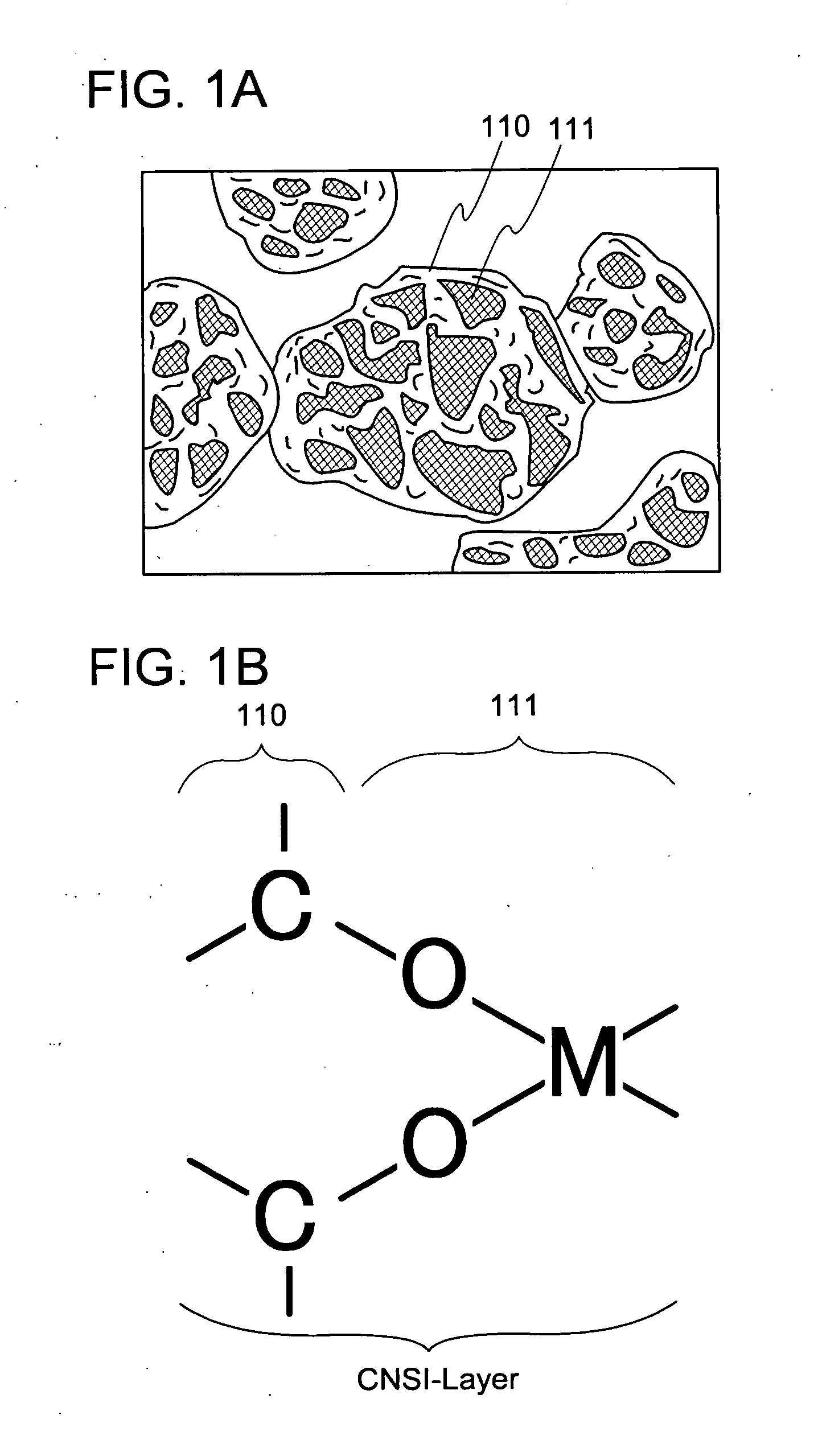
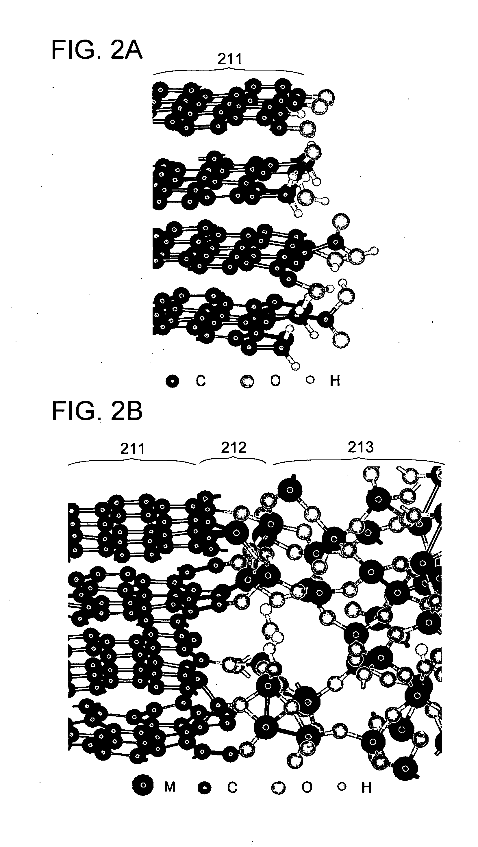
[0047]First, a structural example of a material for an electrode of a power storage device of this embodiment will be described with reference to FIGS. 1A and 1B, FIGS. 2A and 2B, and FIG. 3.
[0048]The material for an electrode of a power storage device includes a granular active material 110 as illustrated in FIG. 1A.
[0049]The shape of the granular active material 110 is not particularly limited. The granular active material 110 may have a spherical shape (powdered state), a plate-like shape, an angular shape, a column shape, a needle-like shape, or a scale-like shape, for example. Note that a film-like active material may be used instead of the granular active material 110.
[0050]As a material of the granular active material 110, a carbon-based material (e.g., graphite) can be used.
[0051]Graphite is a layered compound in which a plurality of graphene layers is stacked in p...
embodiment 2
[0092]In this embodiment, a negative electrode of a power storage device using the material for an electrode of a power storage device described in Embodiment 1 and a method for forming the negative electrode will be described with reference to FIGS. 5A to 5D.
[0093]As illustrated in FIG. 5A, a negative electrode 200 includes a negative electrode current collector 201 and a negative electrode active material layer 202 provided on one or both surfaces (on the both surfaces in the drawing) of the negative electrode current collector 201.
[0094]The negative electrode current collector 201 is formed using a highly conductive material which is not alloyed with a carrier ion such as lithium. For example, stainless steel, copper, nickel, or titanium can be used. In addition, the negative electrode current collector 201 can have a foil-like shape, a plate-like shape (sheet-like shape), a net-like shape, a punching-metal shape, an expanded-metal shape, or the like as appropriate. The negative ...
embodiment 3
[0116]In this embodiment, a structure of a lithium ion battery as a power storage device and a method for manufacturing the lithium ion battery are described.
(Positive Electrode)
[0117]First, a positive electrode and a method for forming the positive electrode will be described.
[0118]FIG. 6A is a cross-sectional view of a positive electrode 250. In the positive electrode 250, a positive electrode active material layer 252 is formed over a positive electrode current collector 251.
[0119]For the positive electrode current collector 251, a highly conductive material such as a metal typified by stainless steel, gold, platinum, zinc, iron, aluminum, or titanium, or an alloy of these metals can be used. Note that the positive electrode current collector 251 can be formed using an aluminum alloy to which an element which improves heat resistance, such as silicon, titanium, neodymium, scandium, or molybdenum, is added. Further alternatively, the positive electrode current collector 251 may be...
PUM
| Property | Measurement | Unit |
|---|---|---|
| angle | aaaaa | aaaaa |
| particle diameter | aaaaa | aaaaa |
| energy density | aaaaa | aaaaa |
Abstract
Description
Claims
Application Information
 - R&D
- Intellectual Property
- Life Sciences
- Materials
- Tech Scout
- Unparalleled Data Quality
- Higher Quality Content
- 60% Fewer Hallucinations
Browse by: Latest US Patents, China's latest patents, Technical Efficacy Thesaurus, Application Domain, Technology Topic, Popular Technical Reports.
© 2025 PatSnap. All rights reserved.Legal|Privacy policy|Modern Slavery Act Transparency Statement|Sitemap|About US| Contact US: help@patsnap.com


