Lithium secondary cell
a lithium secondary cell, long-life technology, applied in the direction of battery, sustainable manufacturing/processing, final product manufacturing, etc., can solve the problems of deterioration, large reduction in the capacity of the cell, and remarkable deterioration, so as to improve the cycle property, the effect of long life and high capacity
- Summary
- Abstract
- Description
- Claims
- Application Information
AI Technical Summary
Benefits of technology
Problems solved by technology
Method used
Image
Examples
embodiment 1
Producing of Negative Electrode
[0080]A negative electrode active material was obtained by weighting silicon having an average particle diameter of 5 μm and black lead having an average particle diameter of 30 μm in a mass ratio of 90:10, and mixing them by so-called mechanical milling for 24 hours. This negative electrode active material having an average particle diameter D50 of 5 μm and polyimide marketed as “U vanish A” manufactured by Ube Industries, Ltd. were weighted in a mass ratio of 85:15 and were mixed with n-methylpyrrolidone, whereby negative electrode slurry was produced. The negative electrode slurry was applied on copper foil having a thickness of 10 μm, and was dried, and then thermal treatment of 300° C. in nitrogen atmosphere was performed, whereby a negative electrode was formed. Also, with respect to an embodiment using this negative electrode active material, in the section “DISPERSION OF Si IN SiOx” of table 1, “N” was written.
[Formation of Positive Electrode]
[...
embodiments 2 to 13
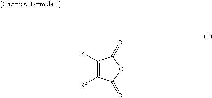
[0087]Except that instead of the compound represented by Chemical Formula 8, compounds shown in Table 1 were used as cyclic acid anhydrides, similarly to Embodiment 1, secondary cells were formed, and cycle characteristics were evaluated. The results are shown in Table 1.
embodiments 14 to 26
[0088]Except that instead of polyimide, polyamide imide (PAI) marketed as “PYROMAX” manufactured by TOYOBO Co., Ltd. was used as the negative electrode binder and instead of the compound represented by Chemical Formula 8, compounds shown in Table 1 were used as cyclic acid anhydrides, similarly to Embodiment 1, secondary cells were formed, and cycle characteristics were evaluated. The results are shown in Table 1.
TABLE 1NEGATIVE ELECTRODEACIDACTIVE MATERIALBINDER FORANHYDRIDEMAINTENANCESWELLINGSI / SIOX / CNEGATIVECHEMICALDISPERSION OFRATIORATIOEMBODIMENT(WEIGHT RATIO)ELECTRODEFORMULASi IN SIOX%EVALUATION%EVALUATION190 / 0 / 10PI8N53B5B290 / 0 / 10PI9N54B4B390 / 0 / 10PI12N56B5B490 / 0 / 10PI13N57B7B590 / 0 / 10PI14N55B7B690 / 0 / 10PI15N57B8B790 / 0 / 10PI16N56B7B890 / 0 / 10PI17N55B7B990 / 0 / 10PI20N58B8B1090 / 0 / 10PI22N60B6B1190 / 0 / 10PI23N61B6B1290 / 0 / 10PI24N56B5B1390 / 0 / 10PI25N55B6B1490 / 0 / 10PAI8N64B5B1590 / 0 / 10PAI9N63B7B1690 / 0 / 10PAI12N66B7B1790 / 0 / 10PAI13N67B5B1890 / 0 / 10PAI14N67B7B1990 / 0 / 10PAI15N71B8B2090 / 0 / 10PAI16N70B6B2190...
PUM
 Abstract
Description
Claims
Application Information
 - R&D
- Intellectual Property
- Life Sciences
- Materials
- Tech Scout
- Unparalleled Data Quality
- Higher Quality Content
- 60% Fewer Hallucinations
Browse by: Latest US Patents, China's latest patents, Technical Efficacy Thesaurus, Application Domain, Technology Topic, Popular Technical Reports.
© 2025 PatSnap. All rights reserved.Legal|Privacy policy|Modern Slavery Act Transparency Statement|Sitemap|About US| Contact US: help@patsnap.com


