Cavity enhanced laser based gas analyzer systems and methods

Active Publication Date: 2014-05-08
LI COR
View PDF8 Cites 19 Cited by
  • Summary
  • Abstract
  • Description
  • Claims
  • Application Information

AI Technical Summary

Benefits of technology

[0004]Embodiments herein provide systems and methods for trace gas detection using a resonance optical cavity. In certain embodiments, enhanced performance is achieved by using a laser coupled to the cavity by optical feedback (OF) as the cavity coupling rate is high and the frequency and phase of the intra-cavity light is well defined. For example, in certain embodiments, optical feedback is used to improve precision an

Problems solved by technology

Both of these methods are also not sensitive to the laser intensity.
In the case of using a single modulator, during the free decay period, the l

Method used


Image

  • Cavity enhanced laser based gas analyzer systems and methods
  • Cavity enhanced laser based gas analyzer systems and methods
  • Cavity enhanced laser based gas analyzer systems and methods

Examples


Embodiment Construction

[0028]According to various embodiments, cavity enhanced absorption spectroscopy systems and methods are provided for detecting trace gases using a resonance optical cavity, which contains a gas mixture to be analyzed, and a laser coupled to the cavity by optical feedback. The cavity can have any of a variety of configurations with two or more mirrors, including for example a linear cavity, a v-shaped cavity and a ring optical cavity. The cavity will have multiple cavity resonant modes, or a comb of frequencies spaced apart, as determined by the parameters of the cavity, including the length of the cavity, as is well known.

System Configurations

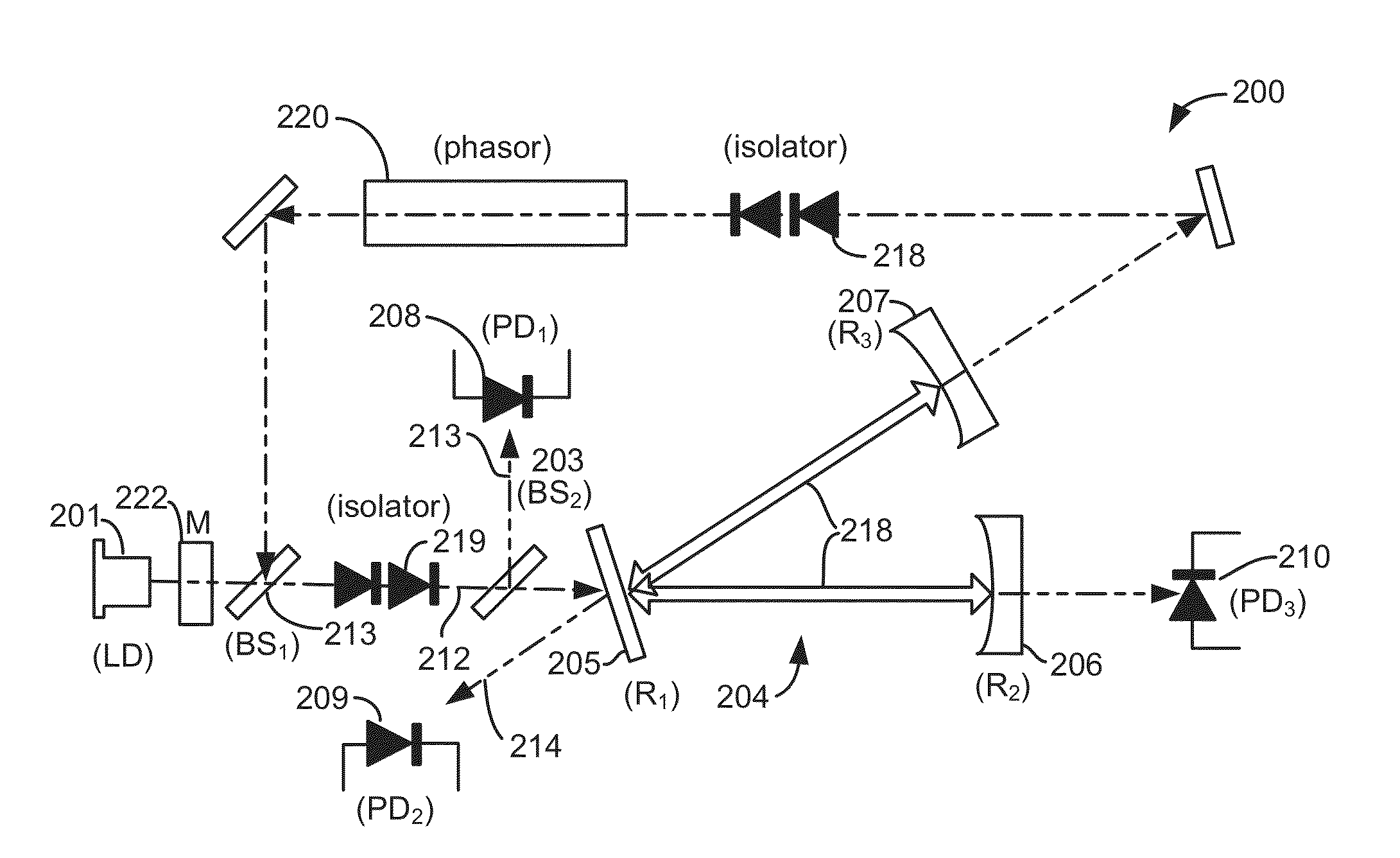
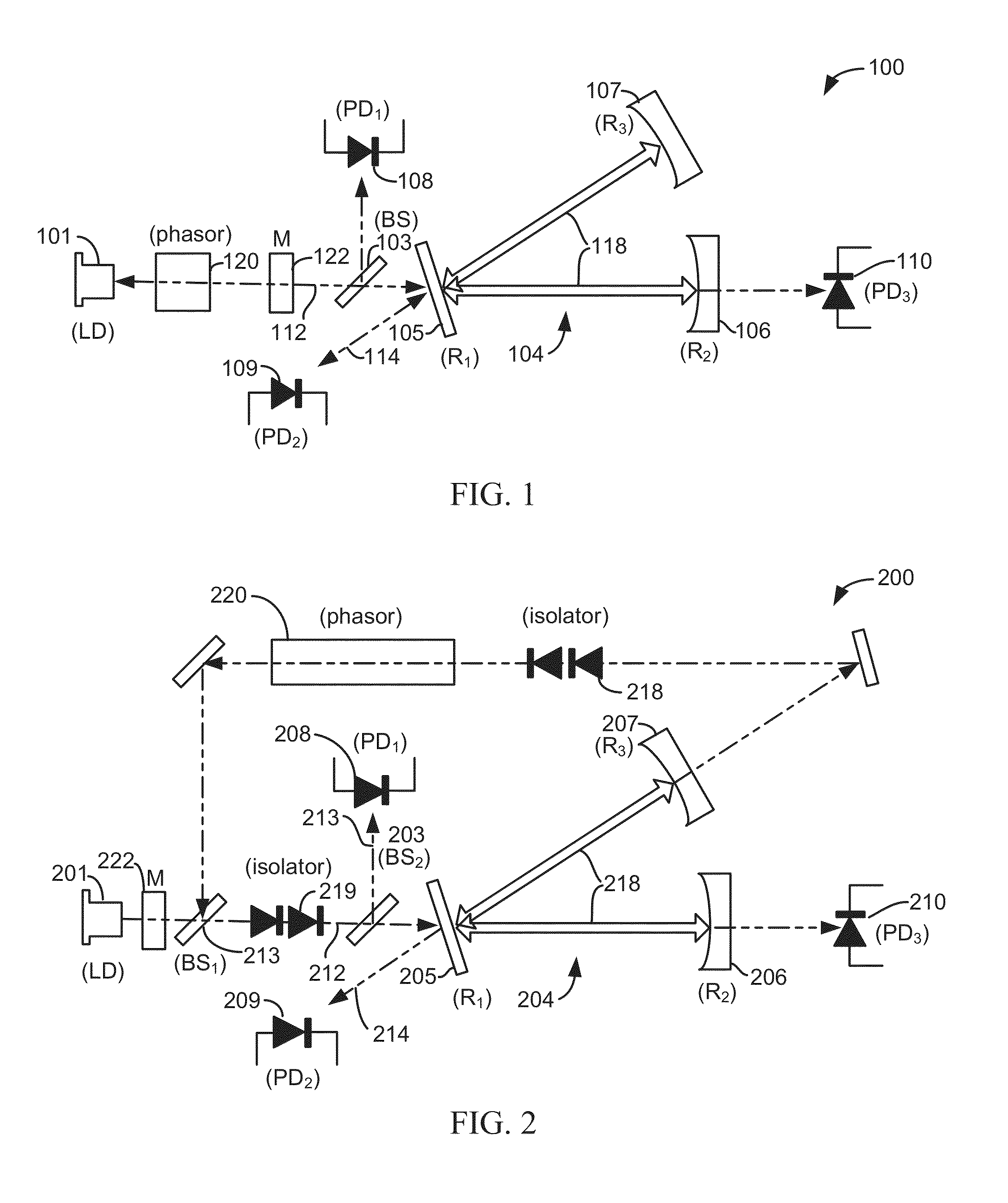
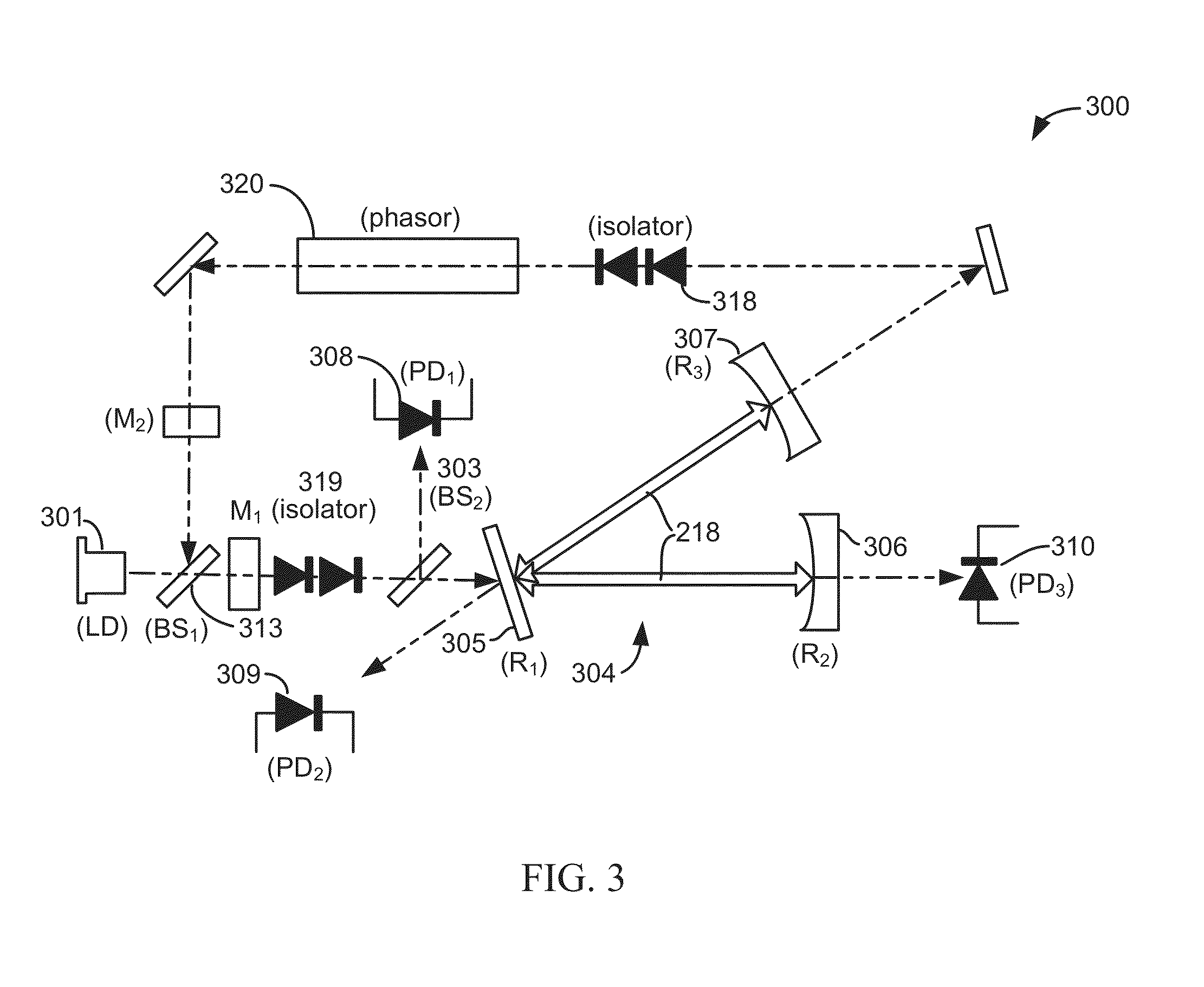
[0029]FIG. 1 illustrates a cavity enhanced absorption spectroscopy (CEAS) system 100 according to one embodiment. As shown, CEAS system 100 includes a light source 101 that emits continuous wave coherent light, such as continuous wave laser light, an optical cavity 104 and three detectors (108, 109 and 110). As shown, cavity 104 is a V-shaped c...


PUM


Abstract

Cavity enhanced absorption spectroscopy systems and methods for detecting trace gases using a resonance optical cavity, which contains a gas mixture to be analyzed, and a laser coupled to the cavity by optical feedback. The cavity has any of a variety of configurations with two or more mirrors, including for example a linear cavity, a v-shaped cavity and a ring optical cavity. The cavity will have multiple cavity resonant modes, or a comb of frequencies spaced apart, as determined by the parameters of the cavity, including the length of the cavity, as is well known. Systems and methods herein also allow for optimization of the cavity modes excited during a scan and/or the repetition rate.

Description

BACKGROUND[0001]The present invention relates generally to trace gas detection and more specifically to cavity enhanced absorption spectroscopy systems and methods for measuring trace gases.[0002]A majority of present instruments capable of implementing cavity ring down absorption spectroscopy methods do not use, or are unable to effectively use, optical feedback to couple a laser to a cavity. This has consequences. For free decay rate cavity ring down spectroscopy (CRDS) methods, poor injection of the laser light to the cavity is achieved. As a result, the ring down rate is rather low (e.g., on the order of hundreds of Hertz). In the case of the phase shift cavity ring down absorption spectroscopy, the laser-cavity injection is also poor, causing additional noise in the measured signals. Also, for both decay rate and phase shift CRDS methods, the laser light coupled to the cavity has a complex frequency-phase characteristic, caused by a phase noise of the laser. The dynamic of the ...

Claims


Application Information

Patent Timeline
IPC IPC(8): G01J3/26G01M11/00
CPCG01M11/005G01J3/26G01J3/021G01J3/42G01N21/3504G01N21/39G01N2021/399
Inventor KACHANOV, ALEXANDERKOULIKOV, SERGUEI
Owner LI COR
Why Eureka
Try Eureka