Combined gasification and power generation

a gasification and power generation technology, applied in steam engine plants, machines/engines, mechanical equipment, etc., can solve the problems the electric power output at the generator terminal, and achieve the effects of reducing the overall increasing the efficiency of the gas turbine compressor, and most efficien

Inactive Publication Date: 2014-05-15
PRAXAIR TECH INC
View PDF21 Cites 8 Cited by
  • Summary
  • Abstract
  • Description
  • Claims
  • Application Information

AI Technical Summary

Benefits of technology

The patent text describes how a gas turbine and an air separation unit work together to improve their efficiency and reduce energy consumption. By operating the gas turbine at a point where it can compress air, it can supply air to the air separation unit while also increasing the efficiency of the gas turbine compressor. This results in lower fuel and power consumption, and a reduction in the size and power consumption of equipment used in fuel production.

Problems solved by technology

As less air is compressed a larger fraction of the gas turbine expander power goes toward driving the air compressor therefore reducing the overall efficiency of the gas turbine as well as the electric power output at the generator terminal.

Method used


Image

  • Combined gasification and power generation
  • Combined gasification and power generation
  • Combined gasification and power generation

Examples


Embodiment Construction

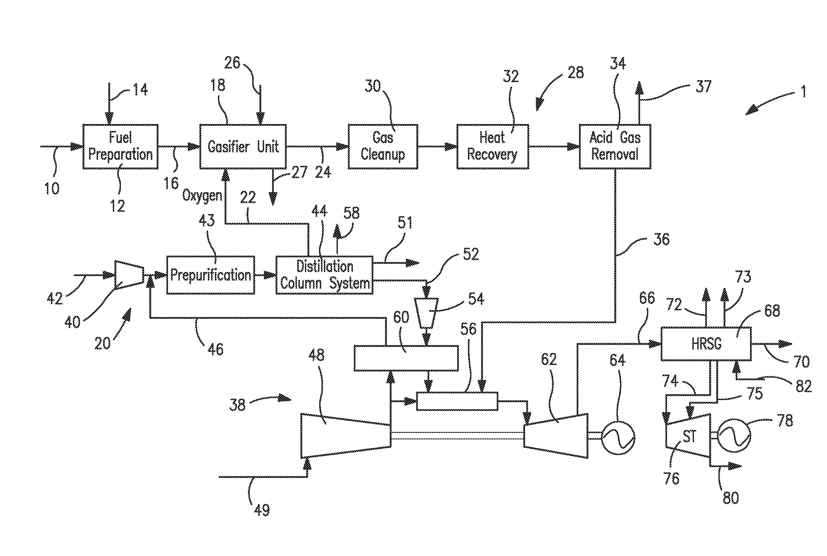
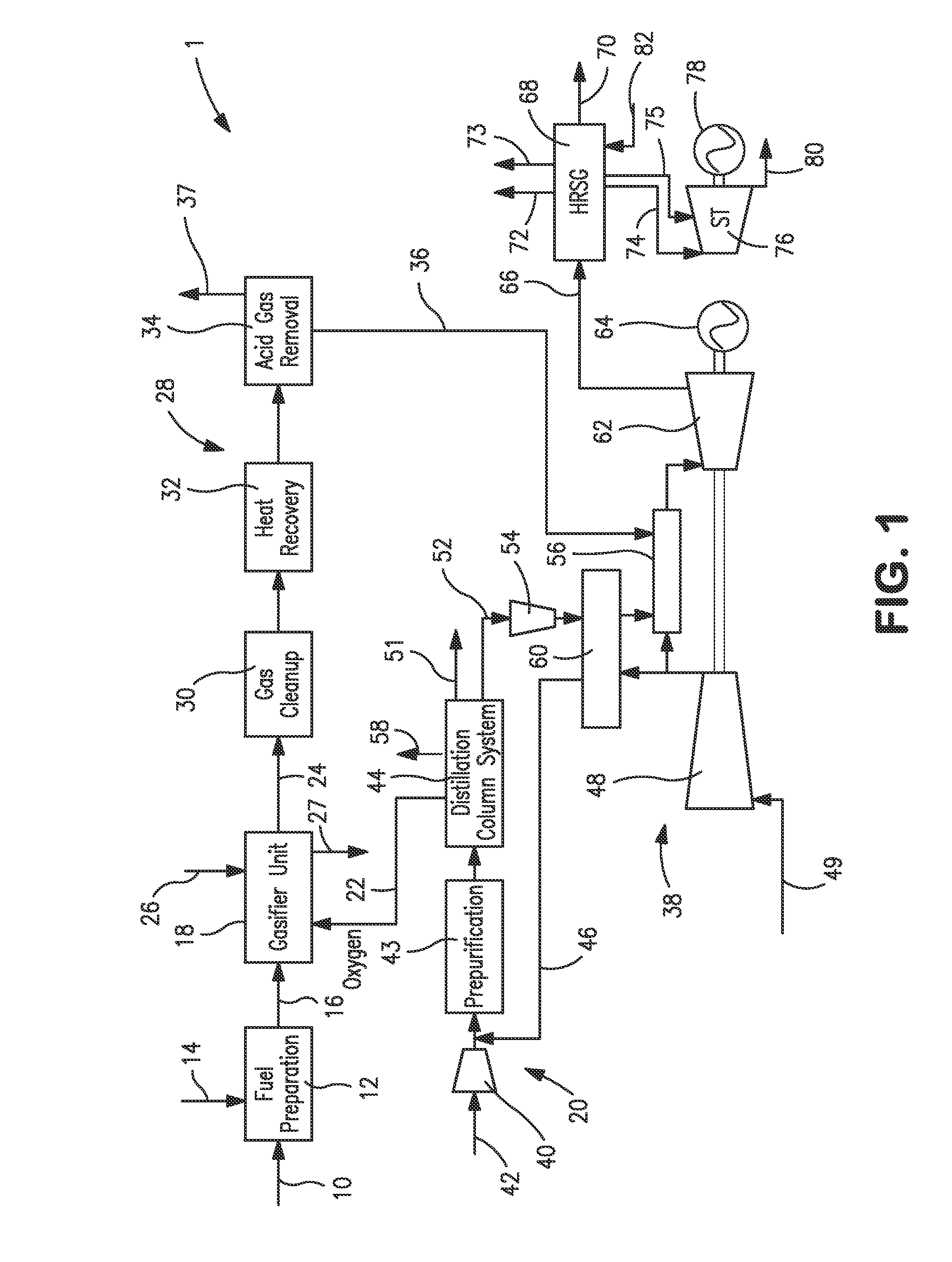
[0021]With reference to FIG. 1, an installation 1 is illustrated that is designed to gasify coal 10 and generate electrical power. Such an installation is an IGCC facility.

[0022]The coal is typically delivered to the project site by rail or barge and then unloaded by equipment such as trestle bottom dumpers, bucket barge unloaders into receiving hoppers. Coal from the hoppers is fed directly into a vibratory feeder and discharged onto a belt conveyor. Conveyors convey the coal to the coal stacker, which transfers the coal to either the long-term storage pile or to the reclaim area. The reclaimer loads the coal into vibratory feeders located in the reclaim hopper under the pile. The feeders transfer the coal onto a belt conveyor that transfers the coal to the coal surge bin located in the crusher tower. If installation 1 is located in close proximity to the coal mine, the coal receiving and handling subsystem would be simplified. For example, no long-term storage would be required. T...


PUM


Abstract

A combined gasification and electric power generation method wherein between 30.0 and 60.0 percent of the compressed air required by an air separation unit supplying oxygen to a gasifier and nitrogen to gas turbine(s) is extracted from a compressor of the gas turbine(s). An installation, including the gas turbine(s), the air separation unit, a gasifier and a gas conditioning system for producing gas turbine fuel, has a design point of ambient temperature and pressure and net power output for producing the electric power required by a captive user. The gas turbine(s), at the design point, have a capacity to compress air from the compressor thereof, at a rate between 4.8 and 6.0 times the total molar flow rate of air required by the air separation unit and the compressor of the gas turbine(s) is operated at no less than 90.0 percent of its capacity at the design point.

Description

RELATED APPLICATIONS[0001]This application claims the benefit of U.S. Provisional Application Ser. No. 61 / 725,766, filed on Nov. 13, 2012, which is incorporated herein by reference.FIELD OF THE INVENTION[0002]The present invention relates to a combined gasification and electrical power generation method in which a carbonaceous substance is gasified in a gasifier that is supplied with oxygen generated by a cryogenic air separation plant to produce a synthesis gas that, after processing, is used as a fuel for one or more gas turbines that are supplied with nitrogen from the air separation plant and that are in turn used to generate at least part of the electrical power required for a facility and to supply compressed air to the cryogenic air separation plant.BACKGROUND OF THE INVENTION[0003]Coal can be gasified and electrical power can be generated in what is known in that art as an integrated gasification and combined cycle (IGCC). In IGCC, gasification of the coal or other carbon co...

Claims


Application Information

Patent Timeline
Patent Type & Authority Applications(United States)
IPC IPC(8): F01K23/06F02C3/28
CPCF02C3/28F01K23/068F02C6/18F01K23/067Y02E20/18
Inventor DRNEVICH, RAYMOND FRANCISCHAKRAVARTI, SHRIKAR
Owner PRAXAIR TECH INC
Why Eureka
Try Eureka