Heater device and oscillation apparatus

a technology of oscillation apparatus and heater, which is applied in the direction of fluid heater, light and heating apparatus, combustion regulation, etc., can solve the problems of difficult circuit formation for high temperature, thermal destruction of equipment, and maximum heater electric power, so as to prevent excessive heat generation of heaters and achieve higher output , the effect of preventing excessive heat generation

Active Publication Date: 2014-05-15
NIHON DEMPA KOGYO CO LTD
View PDF2 Cites 4 Cited by
  • Summary
  • Abstract
  • Description
  • Claims
  • Application Information

AI Technical Summary

Benefits of technology

[0009]The temperature detector is configured to detect a temperature of a temperature-controlled object. The heater control circuit is configured to output a control voltage based on a temperature detection value of the temperature detector, and a temperature target value. The heater is configured to cause heat generation by supply of the control voltage from the heater control circuit, and to provide higher output as the control voltage decreases, so as to heat the temperature of the temperature-controlled object to the target temperature. The voltage supply path is configured to supply the control voltage to the heater. The overheat prevention circuit is configured to prevent excessive heat generation of the heater when the heater control circuit becomes abnormal. The overheat prevention circuit includes a positive-temperature-coefficient thermistor and a pull-up resistor. The positive-temperature-coefficient thermistor is interposed in the voltage supply path in a position heated by the heater. The pull-up resistor includes one end connected between the heater and the positive-temperature-coefficient thermistor, and another end connected to a direct current power source. The control voltage to be applied to the heater is restricted to a voltage at a connection point between the positive-temperature-coefficient thermistor and the pull-up resistor when the control voltage from the heater control circuit abnormally decreases.

Problems solved by technology

However, for example, in the case where a heater control is performed with a negative control characteristic in which the supply power of the heater becomes smaller as the control voltage becomes larger, an abnormal drop (for example, to zero) in control voltage due to LSI failure or solder defect may maximize the heater electric power.
This may thermally destroy the equipment.
Also, in the case where a heater control is performed with a positive control characteristic in which the supply power of the heater becomes larger as the control voltage becomes larger, a similar problem occurs.
For example, although it is possible to dispose an external logic circuit that detects a temperature for protection, it is difficult to constitute the circuit for high temperatures.
If this logic circuit operates normally, the circuit size becomes large.
Accordingly, it is difficult to put the logic circuit within a container as an exterior body of electronic equipment and the price becomes higher.
A drawback with a method using a thermal fuse is that usage lifetime is short under higher temperatures in which the atmosphere temperature is, for example, 70 degrees.

Method used


Image

  • Heater device and oscillation apparatus
  • Heater device and oscillation apparatus
  • Heater device and oscillation apparatus

Examples


first embodiment

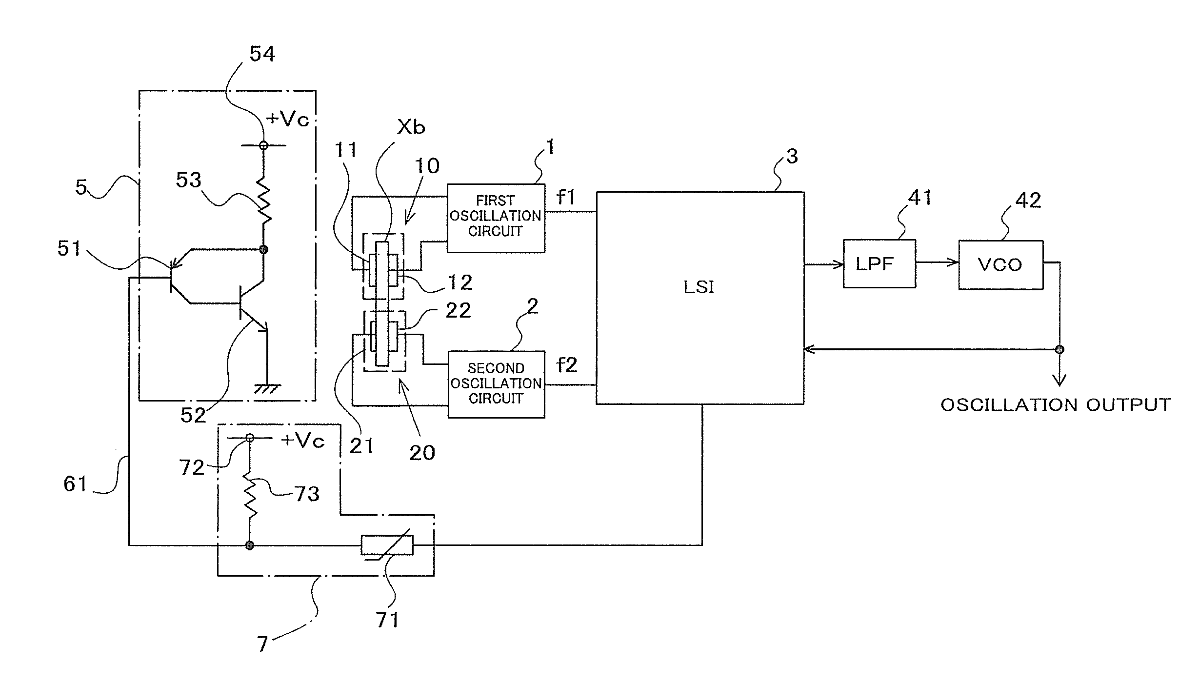
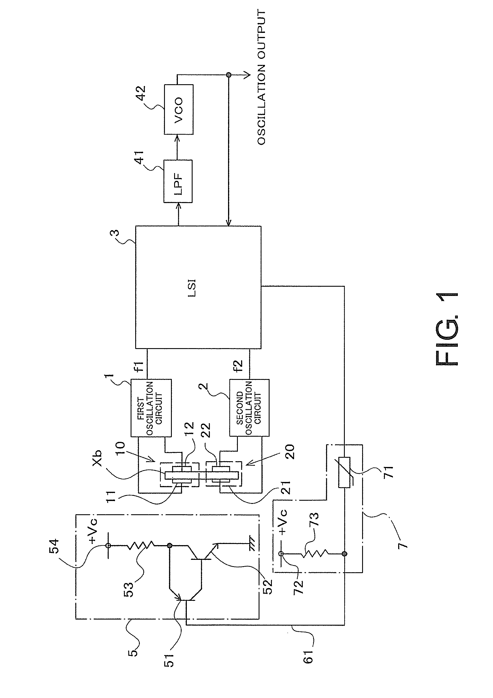
[0020]FIG. 1 illustrates a first embodiment where a heater device of this disclosure is applied to an oscillation apparatus. This oscillation apparatus is constituted as a frequency synthesizer that outputs a frequency signal with a set frequency. The overall configuration of the oscillation apparatus will be briefly described. The oscillation apparatus includes a first crystal unit 10 and a second crystal unit 20. The first crystal unit 10 and the second crystal unit 20 are constituted using a crystal element Xb in common. That is, for example, a strip-shaped area of the crystal element Xb is divided into two in a longitudinal direction, and respective electrodes for excitation are disposed on both front and back surfaces of each divided area (vibration area). Accordingly, the first crystal unit 10 is constituted of one divided area and a pair of electrodes 11 and 12. The second crystal unit 20 is constituted of the other divided area and a pair of electrodes 21 and 22.

[0021]The fi...

second embodiment

[0036]This disclosure is not limited to the heater where its output decreases along with an increase in control voltage. A heater where its output increases along with an increase in control voltage, so to speak, a heater with a positive control characteristic can be used for constituting a similar overheat prevention circuit. FIG. 8 illustrates a main part of an oscillation apparatus using this type of heater 5. This oscillation apparatus employs a configuration where the transistors 51 and 52 are connected in a Darlington configuration. In this case, an increase in base voltage of the transistor 51 increases the current flowing through the transistors 51 and 52, thus increasing the amount of heat generation.

[0037]A digital value for a temperature target value to be input to the heater control circuit 6 is set to, for example, a digital value corresponding to 80° C. in the output characteristic of the frequency difference detector 31 illustrated in FIG. 5. Further, the addition uni...


PUM


Abstract

A heater device includes a temperature detector, a heater control circuit, a heater, a voltage supply path, and an overheat prevention circuit. The overheat prevention circuit includes a positive-temperature-coefficient thermistor and a pull-up resistor. The positive-temperature-coefficient thermistor is interposed on the voltage supply path in a position for being heated by the heater. The pull-up resistor that includes: one end connected between the heater and the positive-temperature-coefficient thermistor, and another end connected to a direct current power source. The control voltage to be applied to the heater is restricted to a voltage at a connection point between the positive-temperature-coefficient thermistor and the pull-up resistor when the control voltage from the heater control circuit is abnormally decreased.

Description

CROSS REFERENCE TO RELATED APPLICATIONS[0001]This application claims the priority benefit of Japan application serial no. 2012-251613, filed on Nov. 15, 2012. The entirety of the above-mentioned patent application is hereby incorporated by reference herein and made a part of this specification.TECHNICAL FIELD[0002]This disclosure relates to a technique that prevents overheating of a heater when a value of a control voltage becomes abnormal in a heater device, and the heater device includes the heater whose heat generation is controlled with the control voltage from a heater control circuit.DESCRIPTION OF THE RELATED ART[0003]As one example of a heater device that includes a heater whose heat generation is controlled with a control voltage from a heater control circuit, a heater device incorporated in an oven-controlled crystal oscillator (OCXO) is illustrated. The OCXO is constituted such that a crystal unit and a heater are disposed within a container, so as to reduce variation in ...

Claims


Application Information

Patent Timeline
Patent Type & Authority Applications(United States)
IPC IPC(8): H03L1/02H05K7/20H05B1/02
CPCH03L1/028H05K7/20H05B1/023H03B5/32H03B5/36H03L1/04H03L7/00H03L7/07
Inventor YORITA, TOMOYA
Owner NIHON DEMPA KOGYO CO LTD
Why Eureka
Try Eureka