Electronic Ballast Having Improved Power Factor and Total Harmonic Distortion

a technology of total harmonic distortion and power factor, applied in the direction of discharge tube/lamp details, energy-saving lighting, sustainable buildings, etc., can solve the problems of long, thin lamps, and inability to fit lamps designed to replace conventional incandescent lamps, and achieve enhanced power factor correction, low cost, and reduced power loss

Active Publication Date: 2014-05-29
LUCIDITY LIGHTS
View PDF5 Cites 25 Cited by
  • Summary
  • Abstract
  • Description
  • Claims
  • Application Information

AI Technical Summary

Benefits of technology

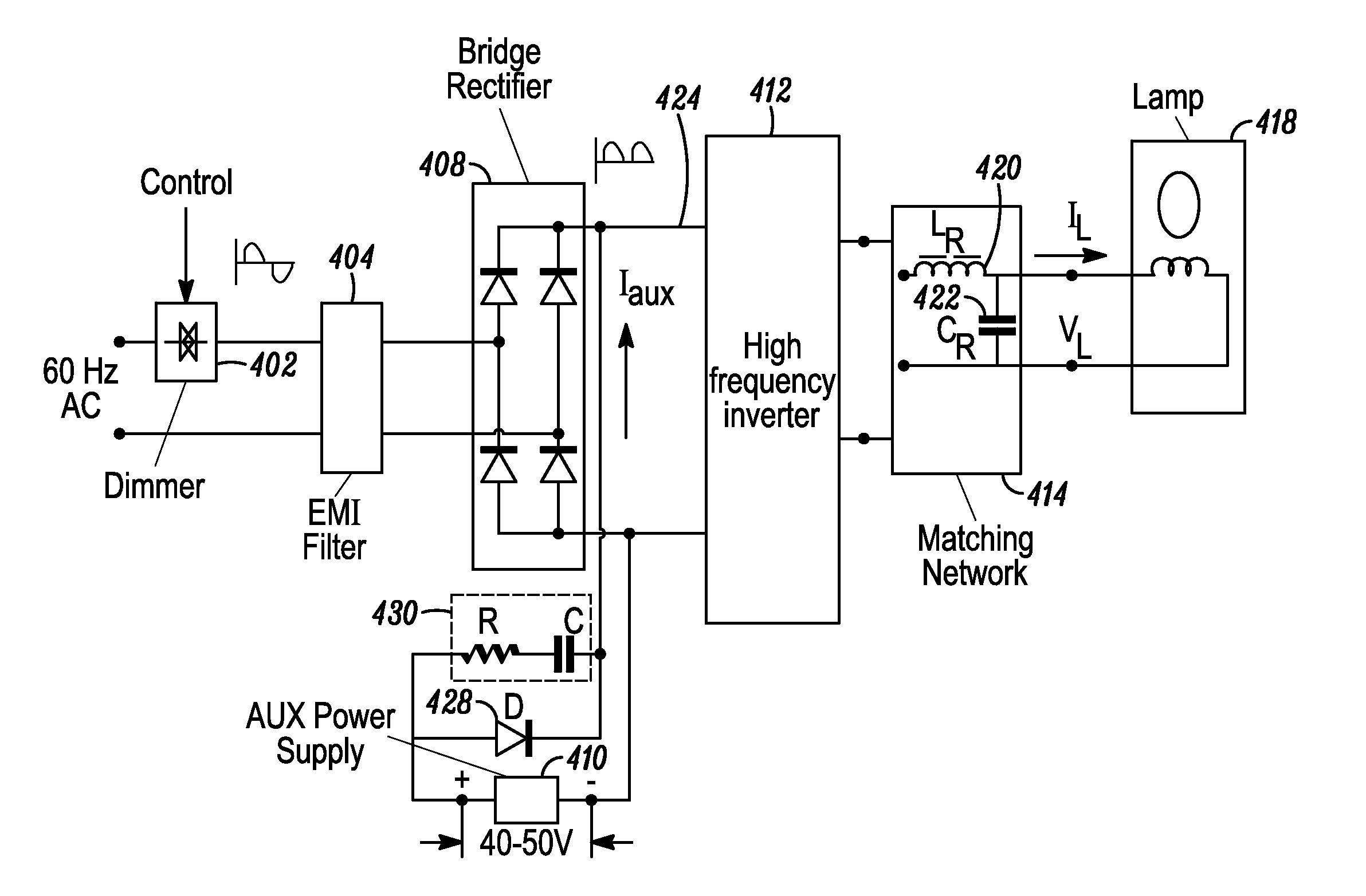
[0019]It is an object of the present invention to provide enhanced power factor correction and low THD for a low cost electronic ballast without an active power factor correction circuit. It is another object of present invention to reduce the power losses caused by high peak input current. It is another object of the invention to provide continuous ballast / lamp operation when dimming by means of a TRIAC, thus avoiding periodic lamp and ballast restarting and the high power losses associated with this mode of operation. It is another object of the invention to provide a low voltage auxiliary power source for ballast control circuitry at no additional cost.
[0020]The invention achieves its goals by providing the ballast with a front end power supply having a bridge rectifier, for rectifying AC to DC, with the traditional electrolytic capacitor typically connected across DC bus replaced by a Passive Valley Fill Circuit using four smaller capacitors that charge in series. This circuit provides continuous ballast and lamp operation when the AC input voltage to the ballast is zero or low. Said Passive Valley Fill Circuit is built as a network comprising four capacitors, each with a voltage rating substantially lower than the DC bus voltage, and 9 diodes (the 4C9D circuit). By having four series charged and parallel discharged capacitors, the total charging capacitance is significantly reduced and total discharging capacitance is significantly increased. The total charging capacitance is one fourth of the charging capacitance of a single capacitor of the same value, and total discharging capacitance is four times the capacitance of a single capacitor of the same value. Peak input current is much lower when four capacitors in series are used. When used with 120V, 60 Hz AC line, the 4C9D circuit provides lower valley fill voltage (about 35-40V DC) than any of the prior art Passive Valley Fill Circuits. Advantageously, the ballast DC to AC inverter can operate from high ripple DC voltage and significantly boost its output voltage at minimum instantaneous DC bus voltage to provide continuous discharge current in the lamp. Therefore, the input current form factor and PF may be significantly improved and the lamp can continuously operate in TRIAC dimming mode without restarting. Electrolytic capacitors have wide tolerance in their characteristics, including the value of their capacitance. In the Passive Valley Fill Circuit, the capacitor voltages are substantially self-equalizing when the capacitors are discharged in parallel to the DC bus. An auxiliary load, such as control circuit, may be powered from any of said capacitors without significant imbalance in the capacitor voltages.

Problems solved by technology

Use of electrodes creates certain problems.
In the case of fluorescent lamps, this leads to long, thin lamps, which are ideal for lighting office ceilings, but are not a good fit for lamps designed to replace conventional incandescent lamps.
A plastic cover shaped like a conventional incandescent lamp is sometimes placed over the bent tubes to provide a more attractive shape, but these covers absorb light, making the lamp less efficient.
Bent and spiral tube lamps also have wasted space between the tubes, making them larger than necessary.
The use of electrodes creates problems other than shape and size.
Electrodes will wear out quickly if the lamp is turned on and off many times, as it would be in a residential bathroom.
In addition, the long thin shape required to use electrodes increases the time required for mercury vapor to diffuse from one part of the tube to another, leading to the long warm-up times we associate with many compact fluorescent lamps.
While this is not a concern with typical fluorescent lamps, it can be a problem with other types of discharge lamps.
The lower operating frequency of closed core induction lamps makes them attractive; however, the bulb design required to accommodate the closed core makes them generally unsuitable for replacing standard in incandescent lamps.
In spite of their obvious advantages, there are very few open core induction lamps on the market today.
One reason for the lack of commercially successful products is the cost of the high frequency ballast.
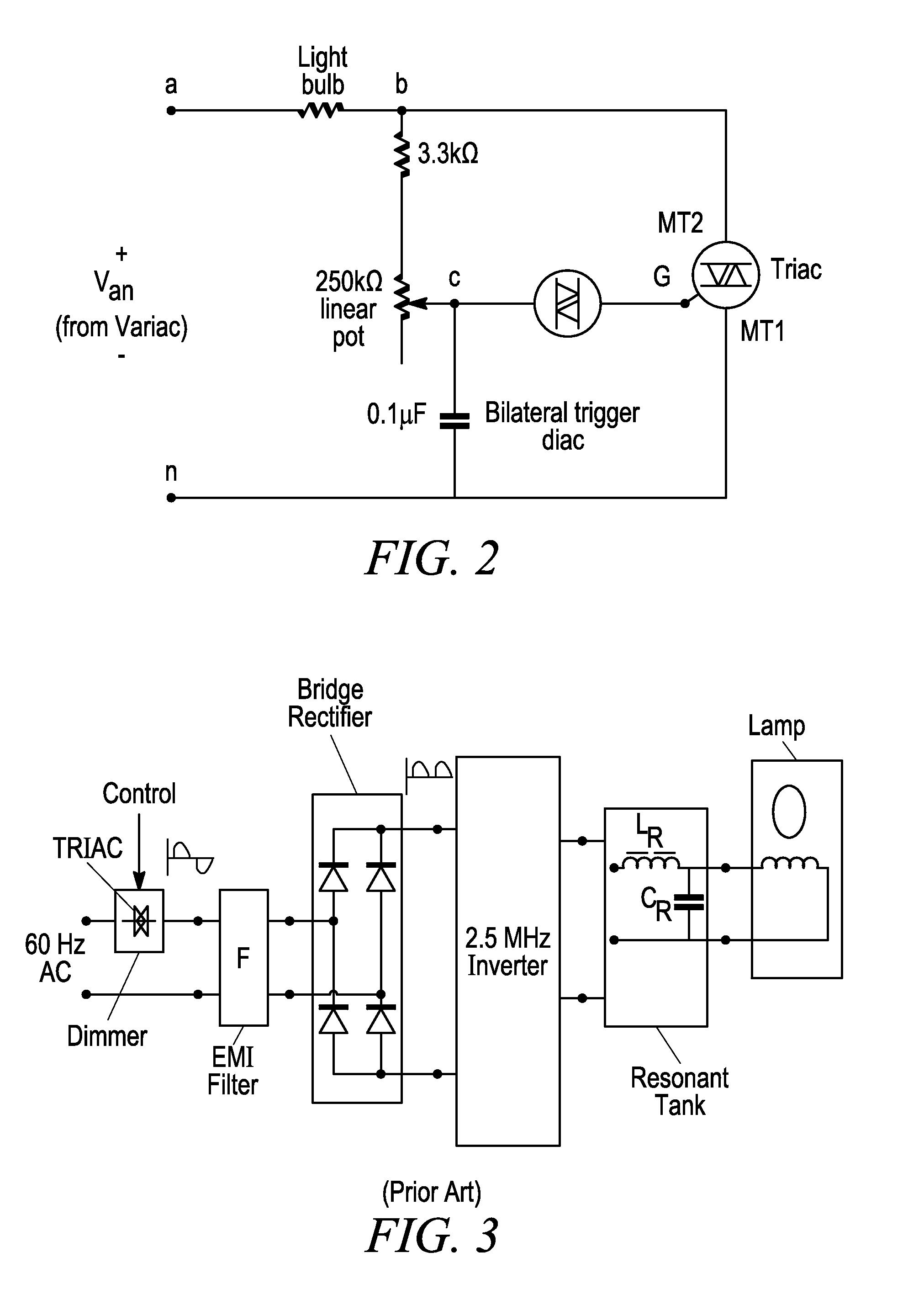
The lack of commercially successful open core induction lamps can be traced to the failure to develop a low cost ballast that can operate in the 2.51 MHz to 3.0 MHz band while meeting all the requirements of the FCC, is small enough to fit into a ballast housing that has the same size and shape as a conventional incandescent lamp, and can be dimmed on conventional TRIAC dimmers found in homes in the U.S. The present disclosure addresses one or more of these issues.

Method used


Image

  • Electronic Ballast Having Improved Power Factor and Total Harmonic Distortion
  • Electronic Ballast Having Improved Power Factor and Total Harmonic Distortion
  • Electronic Ballast Having Improved Power Factor and Total Harmonic Distortion

Examples


Embodiment Construction

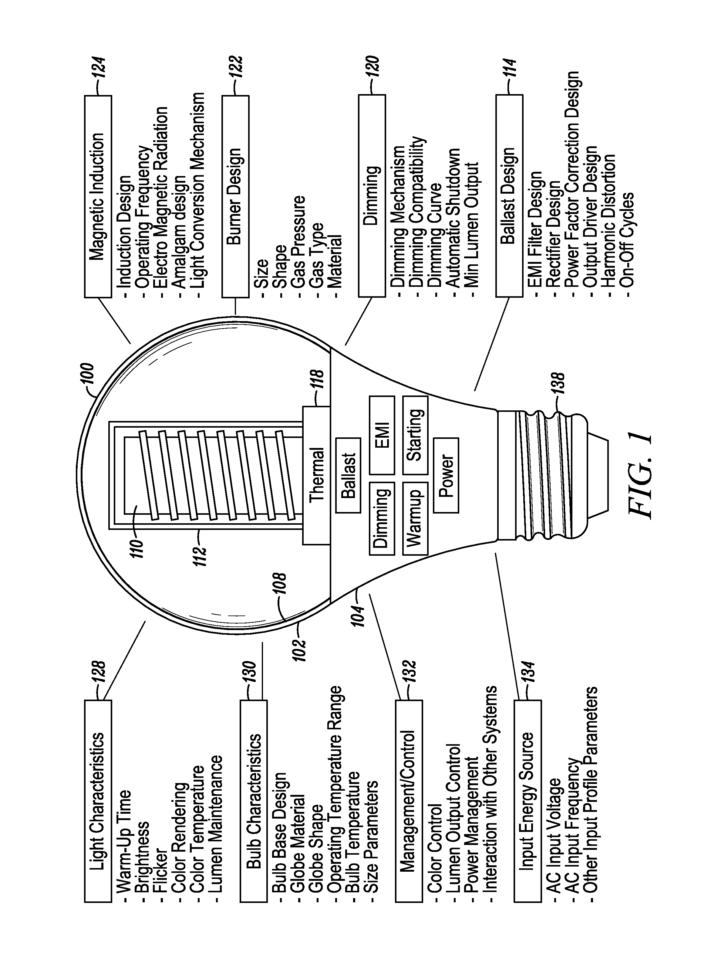
[0044]An induction-driven electrodeless discharge lamp, here after referred to as an ‘induction lamp’, excites a gas within a lamp envelope through an electric field created by a time-varying magnetic field rather than through conductive connections (such as electrodes) that physically protrude into the envelope. Since the electrodes are a limiting factor in the life of a lamp, eliminating them potentially extends the life that may be expected from the light source. In addition, because there are no metallic electrodes within the envelope, the burner design may employ higher efficiency materials that would otherwise react with the electrodes. Embodiments described herein disclose an inductor mounted inside a re-entrant cavity protruding upward within the burner envelope, where the inductor is at least one coil, which may be wound around a core of magnetizable material suitable for operation at the frequency of the time-varying magnetic field, such as ferrite or iron powder, to form ...


PUM


Abstract

An electronic ballast for driving a gas discharge lamp includes an EMI filter, a bridge rectifier coupled to a DC bus without a conventional electrolytic capacitor, a passive valley fill circuit built as a network having 4 charge/discharge energy storage capacitors and 9 diodes (4C9C), and a resonant DC to AC high frequency inverter for powering gas discharge lamp. The 4C9D circuit divides the rectified peak voltage by four and the low output voltage of the circuit is used to provide continuous lamp operation. The result is a ballast having substantially improved power factor, total harmonic distortion, and current crest factor. The electronic ballast is provided with a dimming capability from a TRIAC based wall dimmer.

Description

CROSS-REFERENCE TO RELATED APPLICATIONS[0001]This application is a continuation-in-part of the following U.S. patent applications, each of which is hereby incorporated by reference in its entirety: U.S. patent application Ser. No. 13 / 684,660 filed Nov. 26, 2012, U.S. patent application Ser. No. 13 / 684,664 filed Nov. 26, 2012, and Ser. No. 13 / 684,665 filed Nov. 26, 2012.BACKGROUND[0002]1. Field[0003]The present invention generally relates to AC to DC front end power supplies with high power factor (PF) and low total harmonic distortion (THD) requirements and, more particularly, to electronic ballasts for powering gas discharge lamps, and especially for electronic ballasts dimmed by TRIAC based wall dimmers.[0004]2. Description of Related Art[0005]Discharge lamps create light by exciting an electrical discharge in a gas that can create visible light. In the case of fluorescent lamps the gas is a mixture of argon, krypton and / or neon, plus a small amount of mercury. Other types of disc...

Claims


Application Information

Patent Timeline
Patent Type & Authority Applications(United States)
IPC IPC(8): H05B41/14
CPCH05B41/2806Y02B20/00
Inventor ALEXANDROV, FELIX I.
Owner LUCIDITY LIGHTS
Why Eureka
Try Eureka