Pollution control system for kiln exhaust

a technology of pollution control system and kiln exhaust, which is applied in the direction of lighting and heating apparatus, separation processes, furnaces, etc., can solve the problems of reducing the thermal efficiency of the unit, reducing the level of emissions currently experienced, and prohibitively expensive existing emissions control technologies in other applications

Inactive Publication Date: 2014-06-19
F L SMIDTH & CO AS
View PDF7 Cites 24 Cited by
  • Summary
  • Abstract
  • Description
  • Claims
  • Application Information

AI Technical Summary

Problems solved by technology

In some cases, the level of emissions currently experienced may not be adequately reduced using existing technologies in order to meet new environmental regulations.
In other cases, existing technologies for emissions controls in other applications are prohibitively costly in industrial applications.
Very few cement and lime kilns have installed specialized controls for emissions of organic compounds.
The devices require a clean fuel for heating, as soot and ash introduced from the fuel can reduce the thermal efficiency of the unit.
These devices are of limited applicability in use with cement and minerals processing systems for several reasons—they are small in size relative to the process gas stream that must usually be treated (requiring multiple, parallel units), the intense oxidizing conditions produced in the unit can oxidize SO2 present in the gas stream to SO3 (which necessitates the use of a wet limestone scrubber or other SO2 control device prior to the RTO), and the use of additional fuel firing for operation will increase emissions of carbon monoxide and carbon dioxide.
Combined, these disadvantages make RTOs very difficult to install in industrial plants such as cement kilns because of the large space required for the RTO and supporting equipment, the high cost of installation, and the high cost of operation.
While this temperature range is conducive to a high activity for the catalyst, these systems often see issues associated with the loading of particulate matter in the exhaust gas stream.
Depending on the catalyst structure in use, any of these compounds can cause degradation of the catalytic effect of the system through de-activation of the surface, poisoning of the catalyst, erosion of the catalytic surface, or the blocking of the catalyst surface from contact with the gaseous constituents.
In addition, the dust content of the gas stream requires larger openings in the catalytic structures in use in these systems, requiring larger catalyst structures to obtain the same catalytic surface as is found in other industrial applications.
The loss in efficiency associated with dust loading therefore leads to higher costs for these systems for design and operation than in comparable industries with low dust loads.
The requirement for a dust collection device such as a filter or precipitator is an added piece of process equipment that comes with installation and long term operating and maintenance expenses.
In addition, the layout requirements of the cement kiln or minerals processing facility will often make it difficult or impossible to fit both the filter or precipitator and a catalytic structure within the confines of available areas for installation.

Method used


Image

  • Pollution control system for kiln exhaust
  • Pollution control system for kiln exhaust
  • Pollution control system for kiln exhaust

Examples


Embodiment Construction

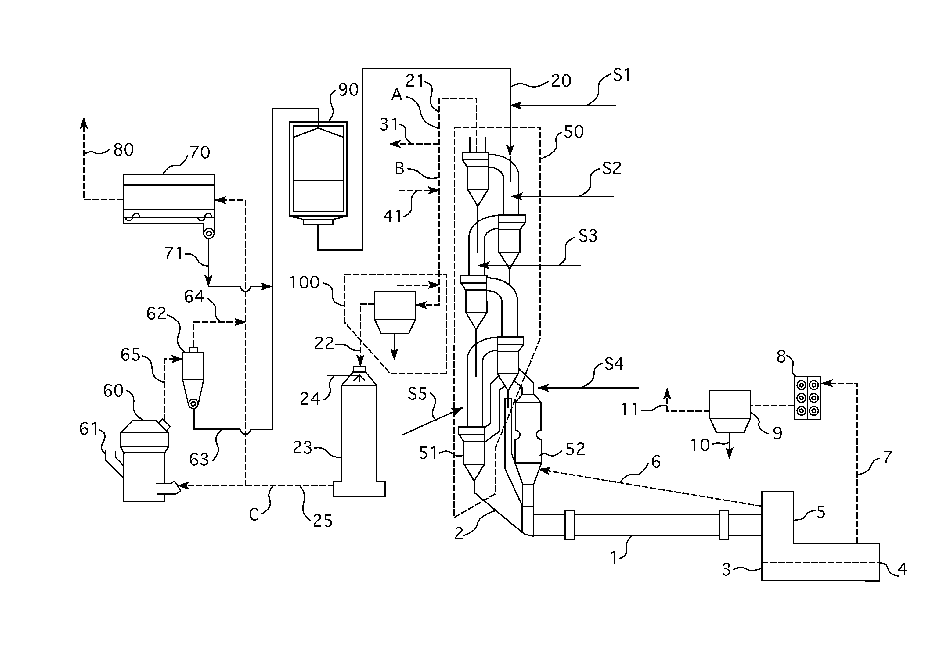
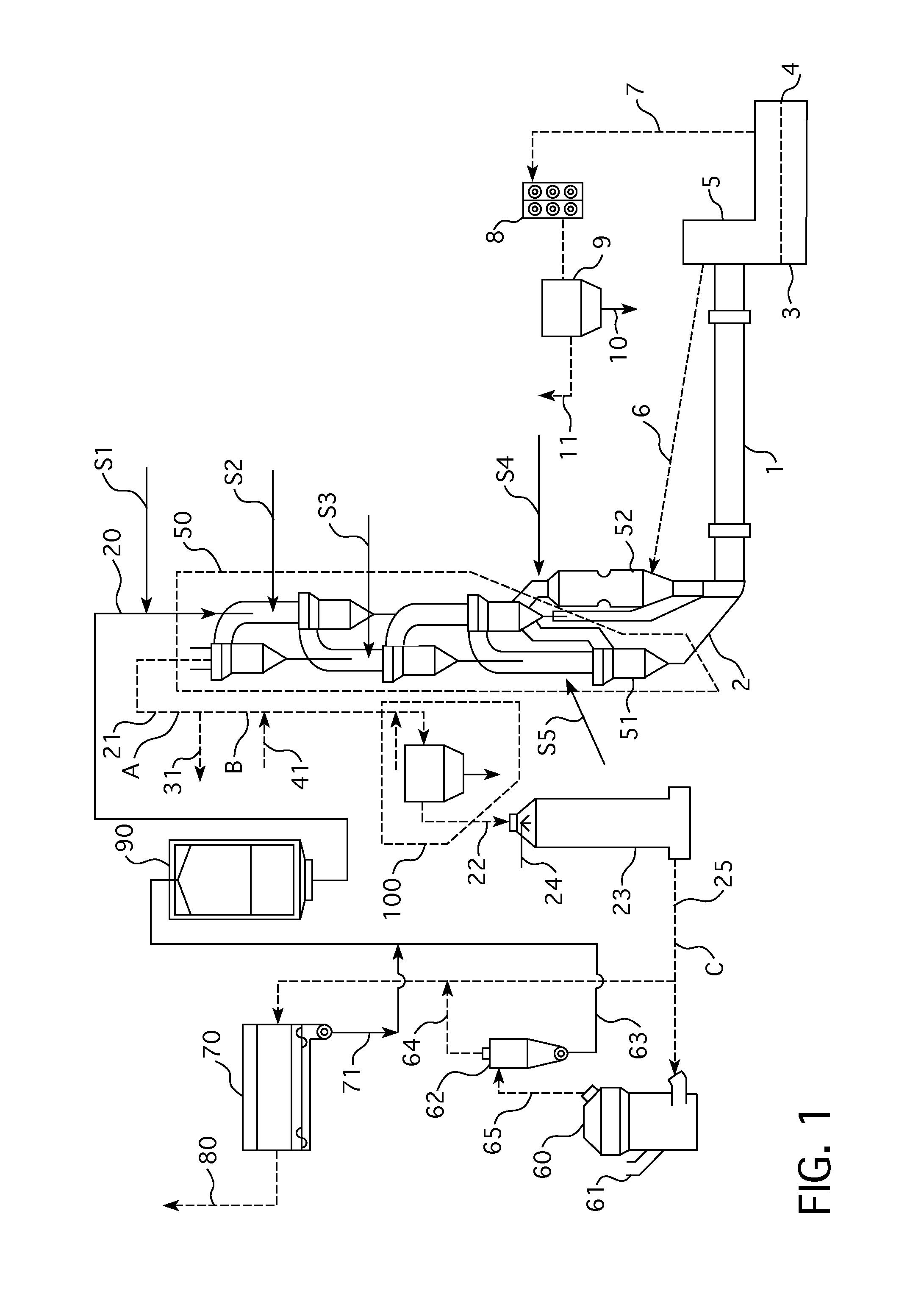
[0016]Although the invention is particularly directed to the reduction in emissions of organic compound emissions, the present invention also applies to the removal of other products of incomplete or partial combustion such as carbon monoxide, condensable VOC's, nitrogen oxides, and dioxin / furans that contaminate manufacturing processes. Many of the organic compounds that this invention is directed towards fall under numerous overlapping categories of compounds, such as Total Organic Carbon (TOC), Total Hydrocarbons (THC), and Volatile Organic Compounds (VOC), and this invention is broadly aimed to the various compounds which are classified under these general categories. Also, while emphasis is placed on a cement manufacturing process, the present invention is applicable to other minerals and kiln manufacturing processes, such as lime manufacturing processes and other industrial processes where very high starting emission levels of these contaminate compounds can not be sufficientl...


PUM

PropertyMeasurementUnit
temperatureaaaaaaaaaa

Abstract

Disclosed is a method and apparatus for the reduction of organic compounds and other emissions from an industrial plant utilizing a cement or minerals kiln that has a high level of organic compound emissions. The invention consists of a filter for the control of particulate emissions which has been treated with a catalyst to provide catalytic destruction of gaseous emissions as process gases are passed through the porous medium of the filter.

Description

BACKGROUND OF THE INVENTION[0001]There is an increasing level of awareness concerning the emission of certain volatile organic compounds (VOCs), combustion byproducts such as carbon monoxide and NOX, and dioxin / furans from industrial plants such as cement manufacturing facilities. With this heightened level of awareness, more stringent environmental regulations are being adopted to ensure low emissions from these industrial plants. In some cases, the level of emissions currently experienced may not be adequately reduced using existing technologies in order to meet new environmental regulations. In other cases, existing technologies for emissions controls in other applications are prohibitively costly in industrial applications. Consequently, there is an interest in developing new systems for controlling these high levels of emissions to meet newly proposed regulations, and that is an object of the present invention.[0002]Very few cement and lime kilns have installed specialized cont...

Claims


Application Information

Patent Timeline
Patent Type & Authority Applications(United States)
IPC IPC(8): F23J15/02F23J15/04
CPCB01D53/46B01D53/86B01D2251/10B01D2251/304B01D2251/404B01D2253/102B01D2257/404B01D2257/502B01D2257/602B01D2257/708B01D2258/0233B01D2259/12C04B7/364F27B7/2033F23J15/006F23J2217/101F23J2217/104F23J2219/10B01D53/8631B01D53/8653F23J15/025F23J15/04
Inventor SCHMIDT, IVERRASMUSSEN, JORN MOLLERPAONE, III, PETER T.SALMENTO, JOHN S.
Owner F L SMIDTH & CO AS
Why Eureka
Try Eureka