Secondary battery, secondary battery module, method for charging the secondary battery and the secondary battery module, method for discharging the secondary battery and the secondary battery module, method for operating the secondary battery and the secondary battery module, power storage system, and method for operating the power storage system

a secondary battery and battery module technology, applied in the field of secondary batteries, can solve the problems of abnormal charging, reduced capacity and resistance of conventional secondary batteries, and short circuit of electrodes and negative electrodes, so as to prevent degradation of secondary batteries and improve the reliability of secondary batteries. the effect of low power consumption

Inactive Publication Date: 2014-07-24
SEMICON ENERGY LAB CO LTD
View PDF25 Cites 13 Cited by
  • Summary
  • Abstract
  • Description
  • Claims
  • Application Information

AI Technical Summary

Benefits of technology

[0014]One embodiment of the present invention can prevent degradation of a secondary battery or the like. One embodiment of the present invention can prevent a reduction in the capacity of a secondary battery or the like due to charging or discharging. One embodiment of the present inventi

Problems solved by technology

The conventional secondary battery has problems of a capacity reduction and a resistance increase due to gradual degradation by repetitive charge and discharge.
However, when the potential of the negative electrode becomes below the allowable value, lithium is deposited on a surface of the negative electrode active material, which indicates abnormal charging

Method used


Image

  • Secondary battery, secondary battery module, method for charging the secondary battery and the secondary battery module, method for discharging the secondary battery and the secondary battery module, method for operating the secondary battery and the secondary battery module, power storage system, and method for operating the power storage system
  • Secondary battery, secondary battery module, method for charging the secondary battery and the secondary battery module, method for discharging the secondary battery and the secondary battery module, method for operating the secondary battery and the secondary battery module, power storage system, and method for operating the power storage system
  • Secondary battery, secondary battery module, method for charging the secondary battery and the secondary battery module, method for discharging the secondary battery and the secondary battery module, method for operating the secondary battery and the secondary battery module, power storage system, and method for operating the power storage system

Examples


embodiment 1

[0037]In this embodiment, examples of a structure of a secondary battery module of one embodiment of the present invention, a method for charging a secondary battery included in the secondary battery module, and methods for charging and discharging the secondary battery module will be described.

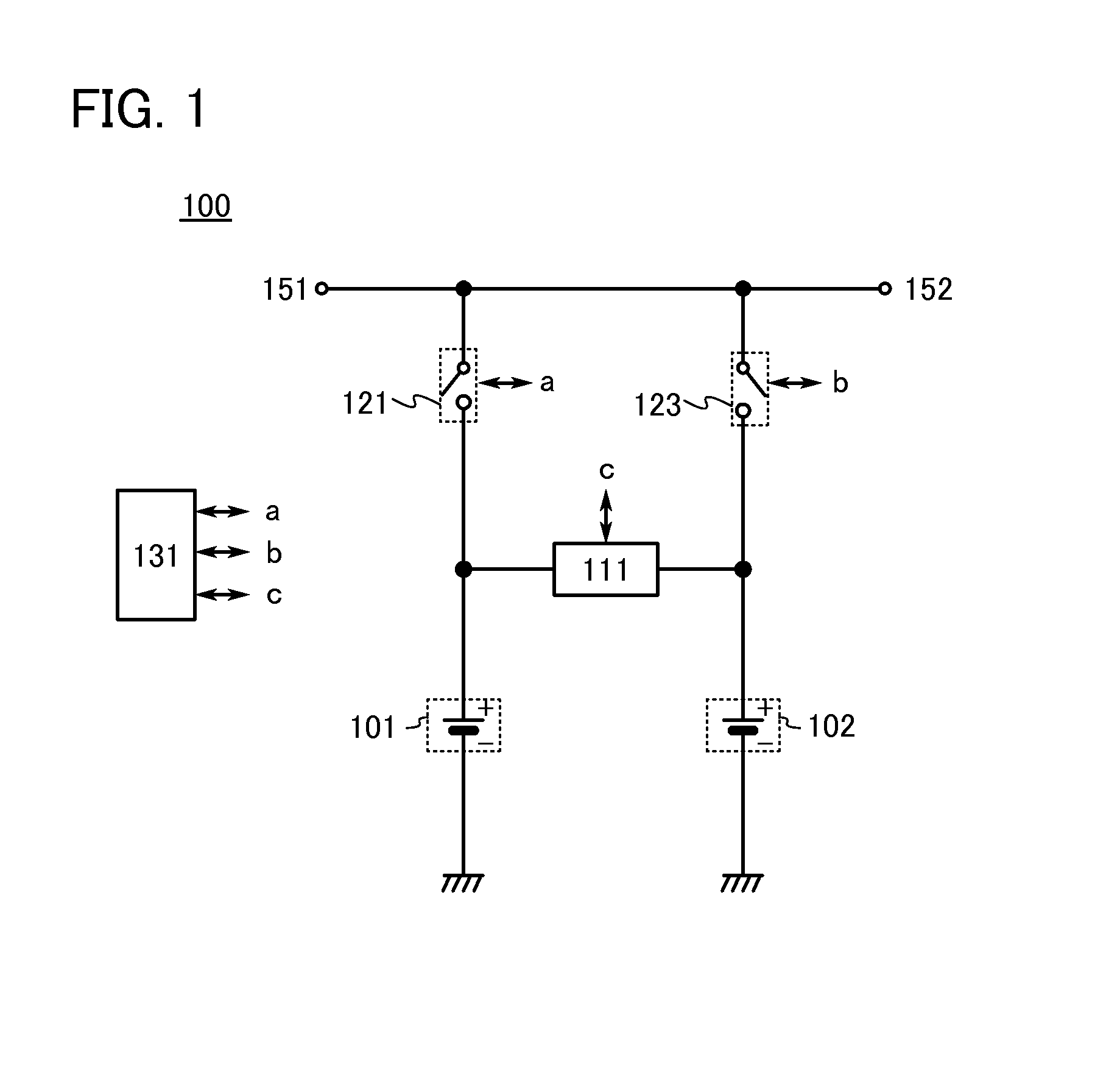
[0038]As illustrated in FIG. 1, a secondary battery module 100 includes a secondary battery 101, a secondary battery 102, a DC / DC converter 111, a switch 121, a switch 123, and a control circuit 131.

[0039]As the secondary battery 101 and the secondary battery 102, secondary batteries such as a lithium-ion secondary battery, a lead storage battery, a lithium-ion polymer secondary battery, lithium batteries, a nickel-metal hydride battery, a nickel-cadmium battery, a nickel-iron battery, a nickel-zinc battery, and a zinc-silver oxide battery; secondary flow batteries such as a redox flow battery, a zinc-chlorine battery, and a zinc-bromide battery; mechanically rechargeable secondary batteries ...

embodiment 2

[0074]In this embodiment, other examples of the secondary battery module of one embodiment of the present invention will be described with reference to FIGS. 6A and 6B, FIG. 7, and FIG. 8.

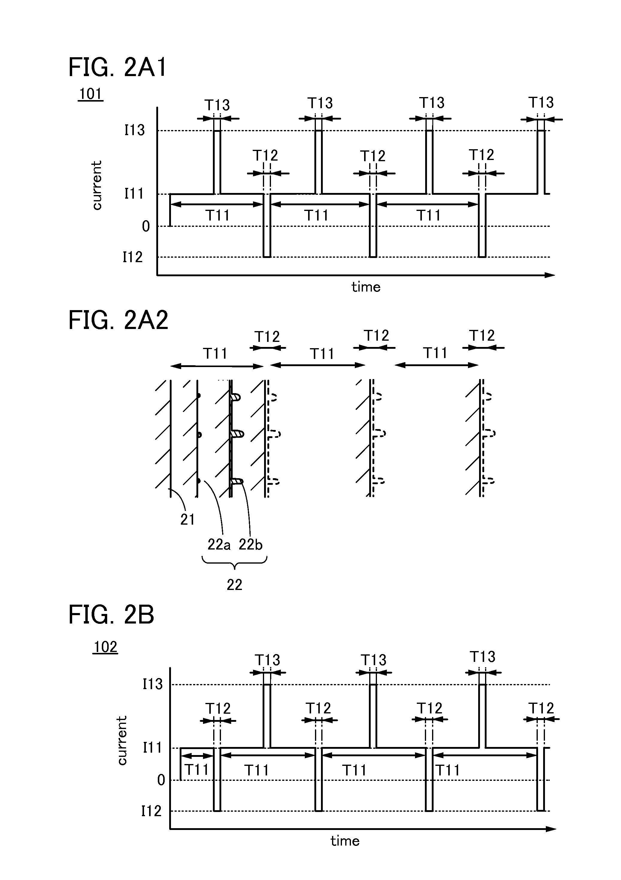
[0075]In Embodiment 1 and FIG. 1, FIGS. 2A1, 2A2, and 2B, FIGS. 3A and 3B, FIGS. 4A and 4B, and FIGS. 5A and 5B, the secondary battery module 100 including two switches, one DC / DC converter, one input terminal, and one output terminal is described; however, one embodiment of the present invention is not limited thereto.

[0076]For example, a plurality of DC / DC converters may be included. The secondary battery module 100 may include a DC / DC converter 112 and a DC / DC converter 113 as in FIG. 6A, for example. In that case, the DC / DC converter 112 and the DC / DC converter 113 are unidirectional DC / DC converters, one of which is set so that current flows in the direction from the secondary battery 101 to the secondary battery 102 and the other of which is set so that current flows in the direction from the...

embodiment 3

[0086]In this embodiment, examples of a DC / DC converter that can be used in one embodiment of the present invention will be described.

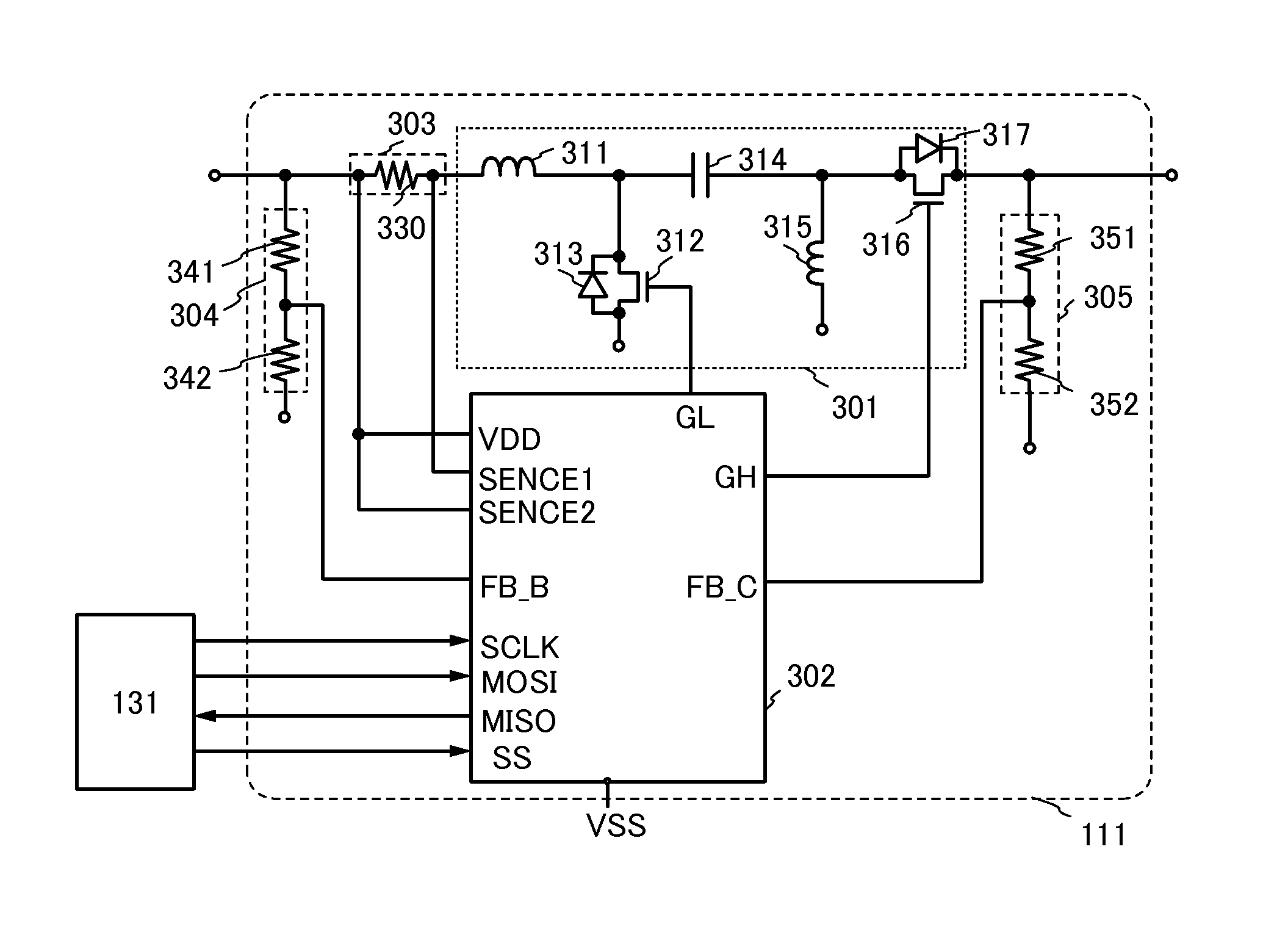
[0087]The DC / DC converter 111 described in Embodiment 1 and illustrated in FIG. 1, FIGS. 2A1, 2A2, and 2B, FIGS. 3A and 3B, FIGS. 4A and 4B, FIGS. 5A and 5B, FIG. 6B, and FIG. 8, has a configuration illustrated in FIG. 9A, for example.

[0088]The DC / DC converter 111 illustrated in FIG. 9A is an example of a single ended primary inductor converter (SEPIC) which is improved so that current flows in both directions. The DC / DC converter 111 includes a power stage 301, a control circuit 302, a current detector 303, a voltage detector 304, and a voltage detector 305.

[0089]The power stage 301 includes an inductor 311, a transistor 312, a diode 313, a capacitor 314, an inductor 315, a transistor 316, and a diode 317. The power stage 301 has a function of controlling the direction of current flowing through the DC / DC converter 111.

[0090]One terminal of the induc...


PUM


Abstract

Degradation of a secondary battery or the like is prevented. A reduction in the capacity of a secondary battery or the like due to charging or discharging is prevented. A secondary battery module in which a secondary battery can be charged in a charging period into which short discharging periods are inserted is provided. A secondary battery module in which a plurality of secondary batteries are connected in parallel, and in a charging period of the secondary batteries, current due to short-time discharging of one secondary battery can be used for charging another secondary battery is provided. To carry out such operation, a secondary battery module includes a plurality of secondary batteries, a DC/DC converter, a switch, and a control circuit.

Description

TECHNICAL FIELD[0001]The present invention relates to a secondary battery, a secondary battery module, a method for charging the secondary battery and the secondary battery module, a method for discharging the secondary battery and the secondary battery module, a method for operating the secondary battery and the secondary battery module, a power storage system, and a method for operating the power storage system.BACKGROUND ART[0002]In recent years, various power storage devices such as secondary batteries including lithium-ion secondary batteries and the like, lithium-ion capacitors, and air cells have been actively developed. In particular, demand for lithium-ion secondary batteries with high output and high energy density has rapidly grown with the development of the semiconductor industry, for electrical appliances, for example, portable information terminals such as mobile phones, smartphones, and notebook computers, portable music players, and digital cameras; medical equipmen...

Claims


Application Information

Patent Timeline
IPC IPC(8): H02J1/00H02J7/00H02J7/02
CPCH02J1/00H01M10/4257H01M10/4207Y02T10/70Y02E60/10H02J7/0013H02J7/0014
Inventor TAKAHASHI, KEIKOYAMA, JUNHIROKI, MASAAKI
Owner SEMICON ENERGY LAB CO LTD
Why Eureka
Try Eureka