Zone plate

Inactive Publication Date: 2014-07-24
HITACHI LTD
View PDF8 Cites 7 Cited by
  • Summary
  • Abstract
  • Description
  • Claims
  • Application Information

AI Technical Summary

Benefits of technology

[0041]By using the zone plate in the invention of this application, it is possible

Problems solved by technology

However, there is no case where an electron

Method used


Image

  • Zone plate
  • Zone plate
  • Zone plate

Examples


first embodiment

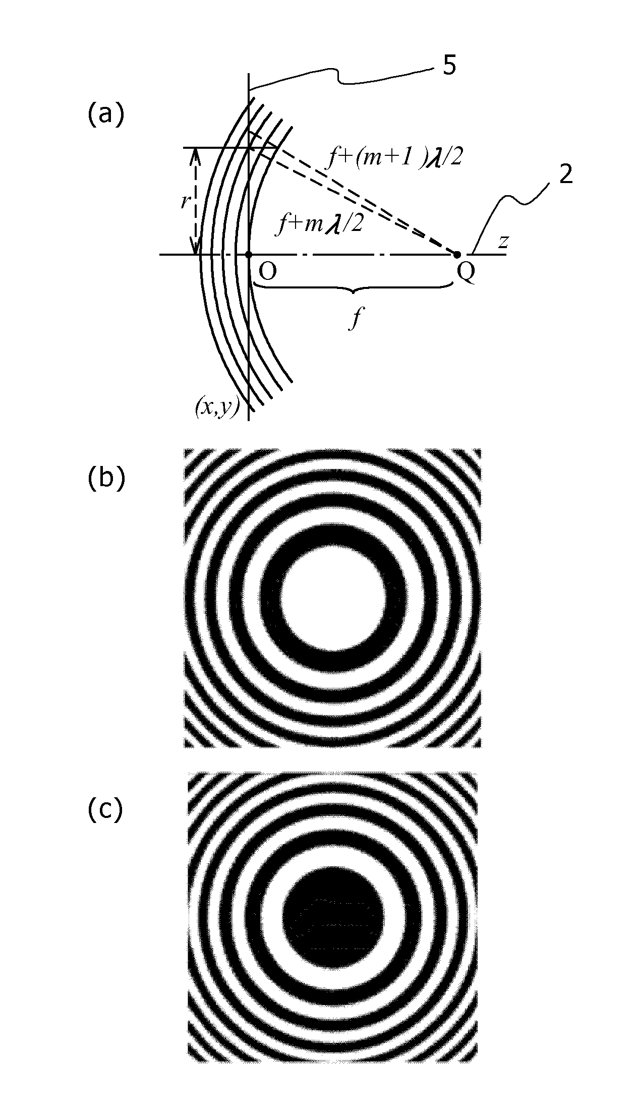
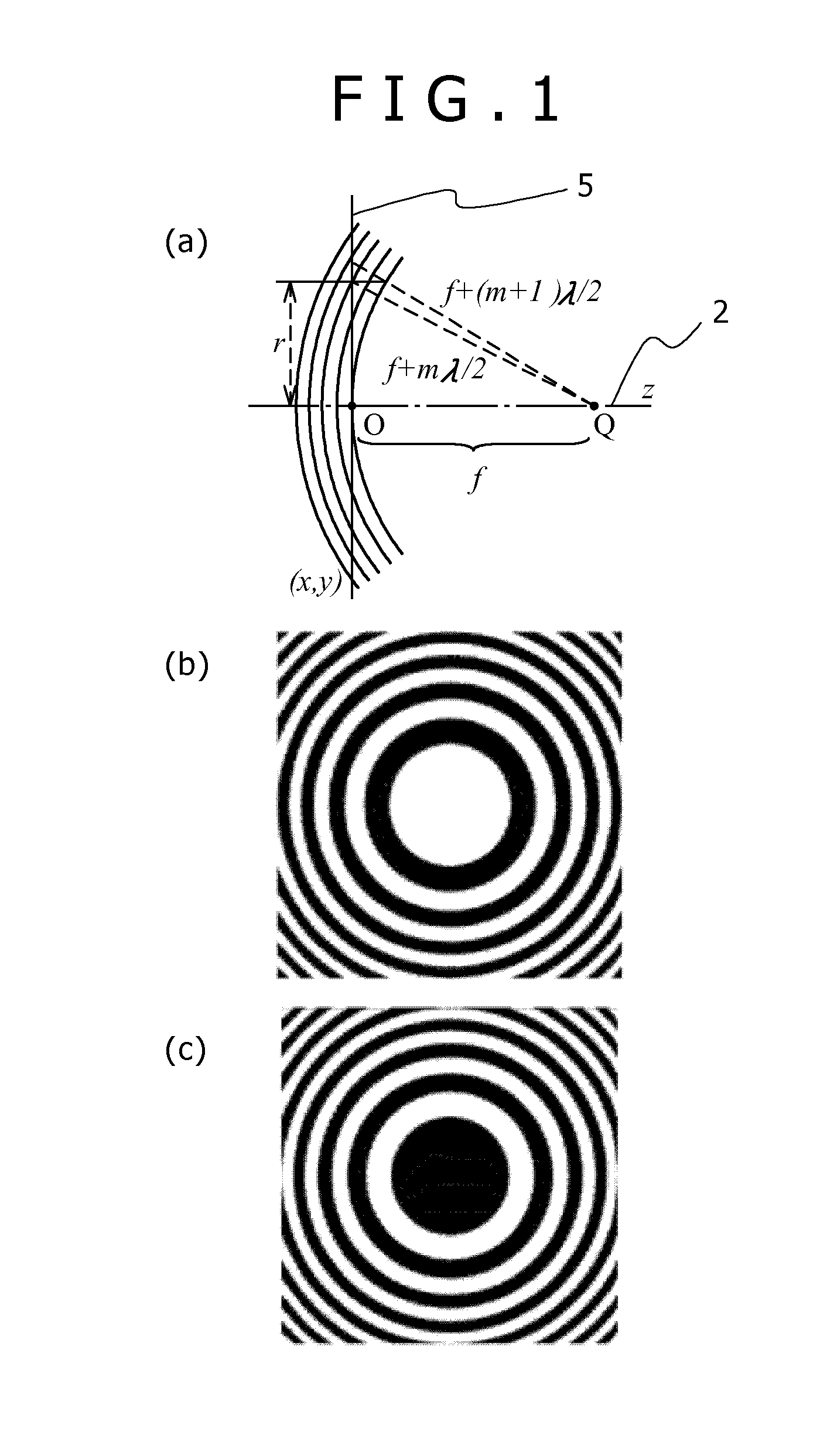
[0091]FIG. 13 is a pattern example of the zone plate for creating a wave front with one spiral axis. The zone plate is set up so that the axis of the spiral wave may be generated at the center of the zone plate, and the spiral center and the center of the zone plate coincide with each other. That is, the grating forms the spiral pattern as a result that a discontinuous point of the grating is located in the center of the zone plate and a nature of the spiral is reflected on the grating.

[0092]FIG. 13 (a) is a case of the spiral degree that is 1, FIG. 13 (b) is a case of the spiral degree that is two, and FIG. 13 (c) is a case of the spiral degree that is three. When the spiral degree is the second order or more, although the zone (grating fringe) of the zone plate makes a point contact in the central part of the spiral pattern, i.e., at a position of the edge dislocation, it is discontinuous as the grating even in this case.

[0093]The spiral patterns shown in FIGS. 13 (a), (b), and (c...

second embodiment

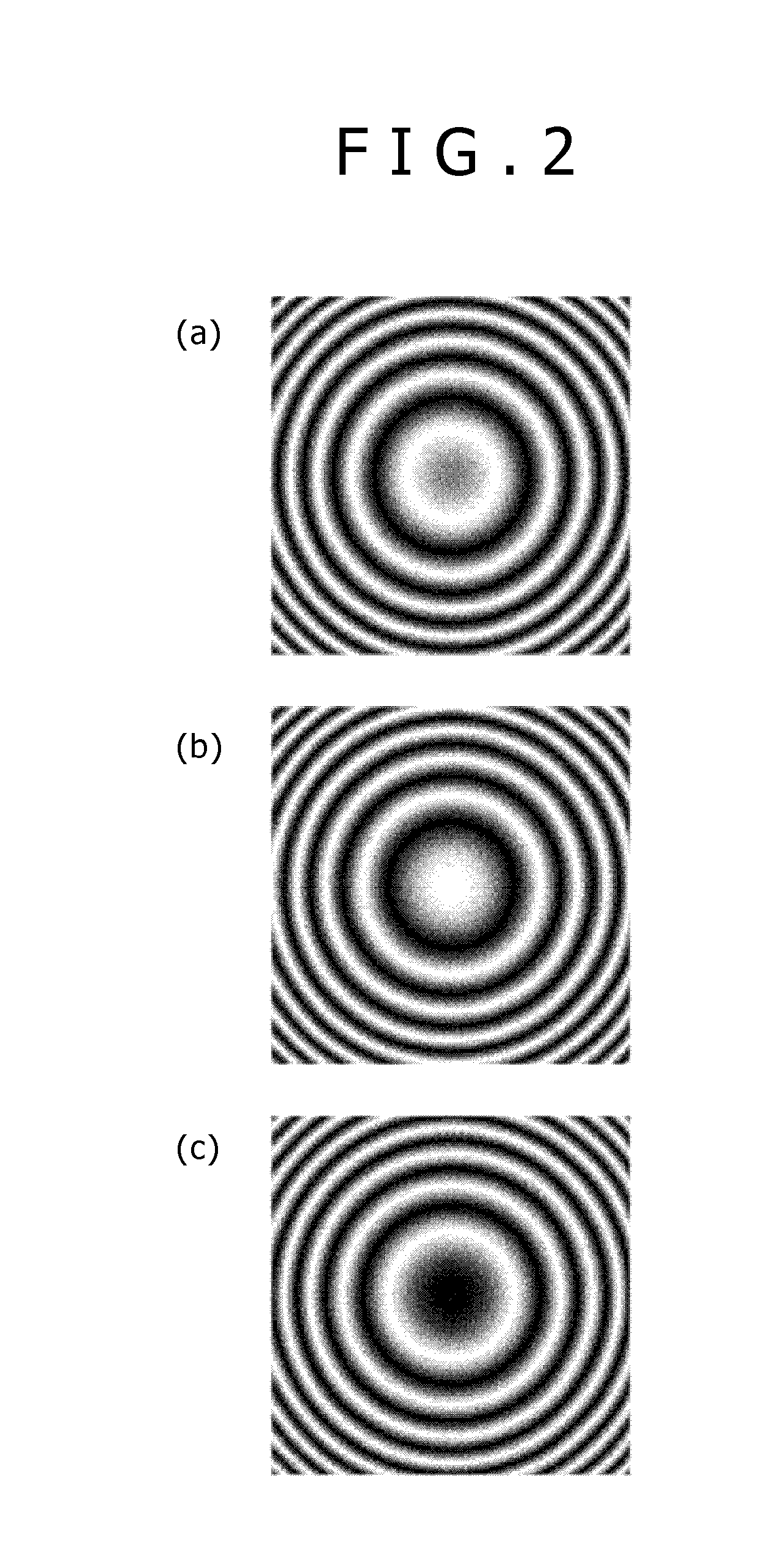
[0096]FIG. 14 illustrates the zone plate when the spiral zone plate shown in FIG. 13 is binarized. Since the zone plate has the spiral pattern, the wave-blocking section is always connected to a periphery of the zone plate. In order to illustrate it, a circumference of the zone plate is enclosed with a black zone in FIG. 14 to indicate a connection with the wave-blocking section of the wave clearly.

[0097]That is, in the zone plate having the spiral pattern, the special supporting substrate, the support rod, or the like for holding a wave-blocking section in space is not needed, and it becomes possible to hold the blocking section, as it is, in space because of rigidity of the material itself that forms the blocking section. This is a large advantage practically in the electron ray having a large interaction with the material that induces the supporting substrate or the support rod to produce an artifact, and other rays.

[0098]FIG. 14 (a) is a case of a spiral degree of 1, FIG. 14 (b)...

third embodiment

[0102]FIG. 15 shows an initial phase of the spiral wave that the spiral zone plate generates, in other words, a pattern of the zone when the initial phase of the edge dislocation is varied. Although FIG. 15 (a) coincides with FIG. 13 (a), the initial phase of the spiral wave is varied by 2π / 3 in FIG. 15 (b) and FIG. 15 (c), which is reflected on a start of wind of the spiral in a central part of the zone plate. If the zone plates as shown in FIG. 15 in which the initial phases of multiple spiral waves are supposed are prepared, it will become possible to control the initial phase of the spiral wave without mechanically rotating the zone plate.

[0103]The changes of the spiral pattern shown in FIGS. 15 (a), (B), and (c) correspond to cases where values of the parameter Φm, expressing the initial phase of the spiral wave are zero, 2π / 3, and 4π / 3 among the patterns of the interference fringe expressed by Formula 12 and Formula 14, respectively.


PUM


Abstract

Although, conventionally, there were two methods, (1) a wave was transmitted through a spiral phase plate and (2) a diffraction grating containing an edge dislocation was used, they incurred complication of a configuration and securement of a larger amount of space and were not efficient because each of the spiral wave generation methods needed an incident wave to be a plane wave and at least one time of imaging is necessary at the time of wave irradiation on an observation object. In order to efficiently generate the spiral wave having a sufficient intensity, a structure of edge dislocation is taken in into a pattern of the zone plate and a spiral pattern containing a discontinuous zone is formed. Moreover, a thickness and a quality of material that change the phase of the wave by an odd multiple of π are selected for a material of the wave-blocking section in the pattern.

Description

TECHNICAL FIELD[0001]The present invention relates to an optical element used in order to generate a spiral wave and its pattern.BACKGROUND ART<Zone Plate>[0002]A zone plate is an optical element called an annular zone plate of Fresnel, and is an optical element having a function of converging or diverging a wave using a diffraction phenomenon. As shown in FIG. 1 (a), when a point light source of wavelength λ is placed at a point Q away from the screen by a distance f on an optical axis 2, denoting a distance from an intersection O of the screen 5 and the optical axis 2 by r(x, y), the zone plate has a structure that divides the screen so that the distance from the point Q to the screen may become f+λ / 2, f+λ, f+3λ / 2, . . . f+mλ / 2, i.e., a structure that is comprised of concentric annular zones whose center is the intersection O of the screen 5 and the optical axis 2 and that are different in width.[0003]Generally, the zone plate that makes a light wave impossible to pass throu...

Claims


Application Information

Patent Timeline
IPC IPC(8): G02B5/18
CPCG21K1/06G02B5/1876G02B27/42G02B27/4233G02B27/4266G02B27/44
Inventor HARADA, KENKOHASHI, TERUO
Owner HITACHI LTD
Why Eureka
Try Eureka