Supercharge Your Innovation With Domain-Expert AI Agents!

Microcontroller for pollution control system for an internal combustion engine

a microcontroller and internal combustion engine technology, applied in the direction of electric control, machines/engines, instruments, etc., can solve the problems of small amount of crankcase oil, harmful to the engine crankcase, and the piston cylinder is not completely sealed off, so as to achieve the effect of negative effects on combustion

Active Publication Date: 2014-07-24
SVMTECH
View PDF6 Cites 7 Cited by
  • Summary
  • Abstract
  • Description
  • Claims
  • Application Information

AI Technical Summary

Benefits of technology

The patent describes a system that controls the timing of opening and closing a valve in an Engine to improve combustion efficiency. By periodically opening and closing the valve at specific engine speeds, the system helps to avoid the negative effects of constantly recycling blow-by gases. This leads to improved fuel economy and reduced emissions.

Problems solved by technology

This keeps the oil in the crankcase rather than allowing it to burn as part of the combustion stroke.
Unfortunately, the piston rings are unable to completely seal off the piston cylinder.
Consequently, small amounts of crankcase oil intended to lubricate the cylinder are instead drawn into the combustion chamber and burned during the combustion process.
Blow-by gases mainly consist of contaminants such as hydrocarbons (unburned fuel), carbon dioxide or water vapor, all of which are harmful to the engine crankcase.
Simply venting these gases to the atmosphere increases air pollution.
Condensed contaminants form corrosive acids and sludge in the interior of the crankcase.
This decreases the ability of the engine oil in the crankcase to lubricate the cylinder and crankshaft.
Degraded oil that fails to properly lubricate the crankshaft components (e.g. the crankshaft and connecting rods) can be a factor in increased wear and tear in the engine, as well as poor engine performance.
Inadequate crankcase lubrication contributes to unnecessary wear on the piston rings which simultaneously reduces the quality of the seal between the combustion chamber and the crankcase.
As the engine ages, the gaps between the piston rings and cylinder walls increase resulting in larger quantities of blow-by gases entering the crankcase.
Too much blow-by gases entering the crankcase can cause power loss and even engine failure.
Moreover, condensed water in the blow-by gases can cause engine parts to rust.
One-way check valve-based PCV valves are unable to account for changes in the quantity of blow-by gases that exist in the crankcase at any given time.
Hence, such an improved PCV valve that solely relies on engine vacuum and a spring-biased restrictor does not optimize the ventilation of blow-by gases from the crankcase to the intake manifold, especially in situations where the vehicle is constantly changing speeds (e.g. city driving or stop and go highway traffic).
But, a spring-based PCV valve is unable to account for the difference in blow-by gas production between 2,500 rpm and 900 rpm because the spring-based PCV valve experiences a similar pressure differential between the intake manifold and the crankcase at these different engine speeds.
As the vehicle accelerates blow-by gas production increases, but the engine vacuum decreases due to the increased engine load.
Thus, the spring based PCV valve may vent an inadequate quantity of blow-by gases from the crankcase during acceleration.
Such a spring-based PCV valve system is incapable of venting blow-by gases based on blow-by gas production because the spring only responds to engine vacuum.
Failure to change the lubricating oil at adequate intervals (typically every 3,000 to 6,000 miles) can lead to a PCV valve system contaminated with sludge.
A plugged PCV valve system will eventually damage the engine.
OBD originally illuminated a malfunction indicator light (MIL) for a detected problem, but did not provide information regarding the nature of the problem.
Unfortunately, OBD-I did not succeed at the time as the infrastructure for testing and reporting emissions-specific diagnostic information was not standardized or widely accepted.
Technical difficulties in obtaining standardized and reliable emission information from all vehicles led to an inability to effectively implement an annual testing program.
A problem exists in that all the diagnostic information coming from the OBD-II system is not being used in order to optimize the performance of the engine; specifically with regard to the PCV valve.

Method used


Image

  • Microcontroller for pollution control system for an internal combustion engine
  • Microcontroller for pollution control system for an internal combustion engine
  • Microcontroller for pollution control system for an internal combustion engine

Examples


Embodiment Construction

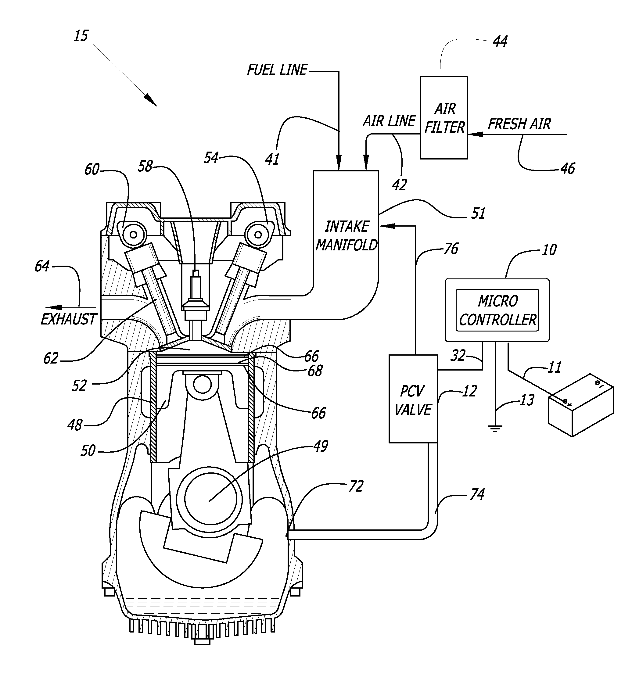
[0031]As shown in the drawings for purposes of illustration, a microcontroller for a pollution control system is referred to generally by the reference number 10. In FIG. 1, the microcontroller 10 is preferably mounted under a hood 14 of an automobile 16. The microcontroller 10 is electrically coupled to one or more of a plurality of sensors that monitor and measure real-time operating conditions and performance of the automobile 16. The microcontroller 10 regulates the flow rate of blow-by gases by regulating the engine vacuum in a combustion engine through digital control of a PCV valve 12. The microcontroller 10 receives real-time input from sensors that might include an engine temperature sensor 18, a spark plug sensor 20, a battery sensor 22, a PCV valve sensor 24, an engine RPM sensor 26, an accelerometer sensor 28, and an exhaust sensor 30. Data obtained from the sensors 18, 20, 22, 24, 26, 28, and 30 by the microcontroller 10 is used to regulate the PCV valve 12, as describe...


PUM


Abstract

A pollution control system for an internal combustion engine includes a microcontroller and a power supply, a plurality of sensors configured to measure operating parameters of the engine, and a PCV valve responsive to a control signal from the microcontroller and configured to regulate a flow rate of blow-by gasses in the engine. The microcontroller includes programmable flash memory connected to a control processor, a power supply input, a sensor input configured to receive data from an engine sensor, and a signal output configured to transmit a signal from the control processor so as to control operation of a PCV valve regulating a flow rate of blow-by gasses in the engine.

Description

FIELD OF THE INVENTION[0001]The present invention generally relates to pollution control systems. More particularly, the present invention relates to a microcontroller for a pollution control system, for an internal combustion engine.BACKGROUND OF THE INVENTION[0002]Basic operation of standard internal combustion (IC) engines varies based on the type of combustion process, the quantity of cylinders and the desired use / functionality. For instance, in a traditional two-stroke engine, oil is pre-mixed with fuel and air before entry into the crankcase where the oil / fuel / air mixture is ignited. In a gasoline engine, fuel is pre-mixed with only air, but is then compressed and ignited by a spark plug that causes the fuel to burn. In a diesel engine, fuel and air are pre-mixed but as there is no spark plug to provide ignition, the fuel / air mixture is ignited by compression in the piston shaft. In each type of IC engine, following fuel ignition, the piston is then pushed downwardly and the e...

Claims


Application Information

Patent Timeline
IPC IPC(8): F01M13/02F02D41/00
CPCF01M13/028F02D41/0025G06F17/30867G06F16/9535F02D2250/08F01M13/023F01M2013/0022F01M13/0011
Inventor MONROS, SERGE V.
Owner SVMTECH
Features
  • R&D
  • Intellectual Property
  • Life Sciences
  • Materials
  • Tech Scout
  • Unparalleled Data Quality
  • Higher Quality Content
  • 60% Fewer Hallucinations
Learn More