Two-stroke air-powered engine assembly

Inactive Publication Date: 2014-08-14
BEIJING XIANGTIAN HUACHUANG AERODYNAMIC FORCE TECH RES INST
View PDF6 Cites 8 Cited by
  • Summary
  • Abstract
  • Description
  • Claims
  • Application Information

AI Technical Summary

Benefits of technology

The patent describes an engine assembly that includes a multiple-column power distributor and an intake speed control valve. The power distributor effectively distributes the engine's power output according to requirements. The intake speed control valve ensures a steady supply of compressed air for the engine to operate at high, intermediate, and low speeds. The technical effect of this invention is the continuous and reliable operation of the engine by effectively distributing high-pressure compressed air to each cylinder.

Problems solved by technology

The engine utilizing fuel as the power source would discharge gas with many harmful substances to pollute the environment because of insufficient fuel combustion on one hand, and on the other hand, the fuel is extracted from petroleum, and the development and utilization of the system using the fuel engine as the power source are increasingly limited by the increasing lack of the petroleum source.
So an impending problem is to develop a new, clean and pollution-free alternative energy source or decrease fuel consumption and emissions as far as possible.
The engine can decrease the fuel consumption partially, but the emission problem isn't solved because of utilizing the fuel supply mode.
One question of this engine is that the compressed air takes a long time to travel from the intake-compression chamber to the expansion and discharge chamber, so it takes a long time to obtain the power source gas for driving piston to do work.
At the same time, the high pressure gas discharged from the expansion and discharge chamber is not used, so the operation efficiency and the continuous working period for one charge of the engine are limited.
The current study is mostly in a theoretical study and conceptual design phase and failed to solve the compressed air emissions and the high-pressure compressed air control and distribution problems.
There is still a long way to go for a product process of the compressed air engine.
Obviously, the four-stroke engine disclosed in the patent document CN101413403A greatly wastes the effective working stroke, and the efficiency of the engine is limited.
And the exhaust gas of the engine can't be recycled and utilized well, and it needs a large enough gas tank to store the high pressure air for working a long time.

Method used


Image

  • Two-stroke air-powered engine assembly
  • Two-stroke air-powered engine assembly
  • Two-stroke air-powered engine assembly

Examples


Embodiment Construction

[0047]The following description is exemplary only, and it is in no way to limit the disclosure, the application and the usage. It should be understood that the corresponding reference symbols indicate the same or corresponding components and characters throughout all drawings.

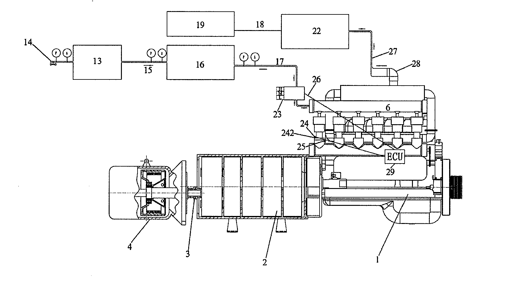
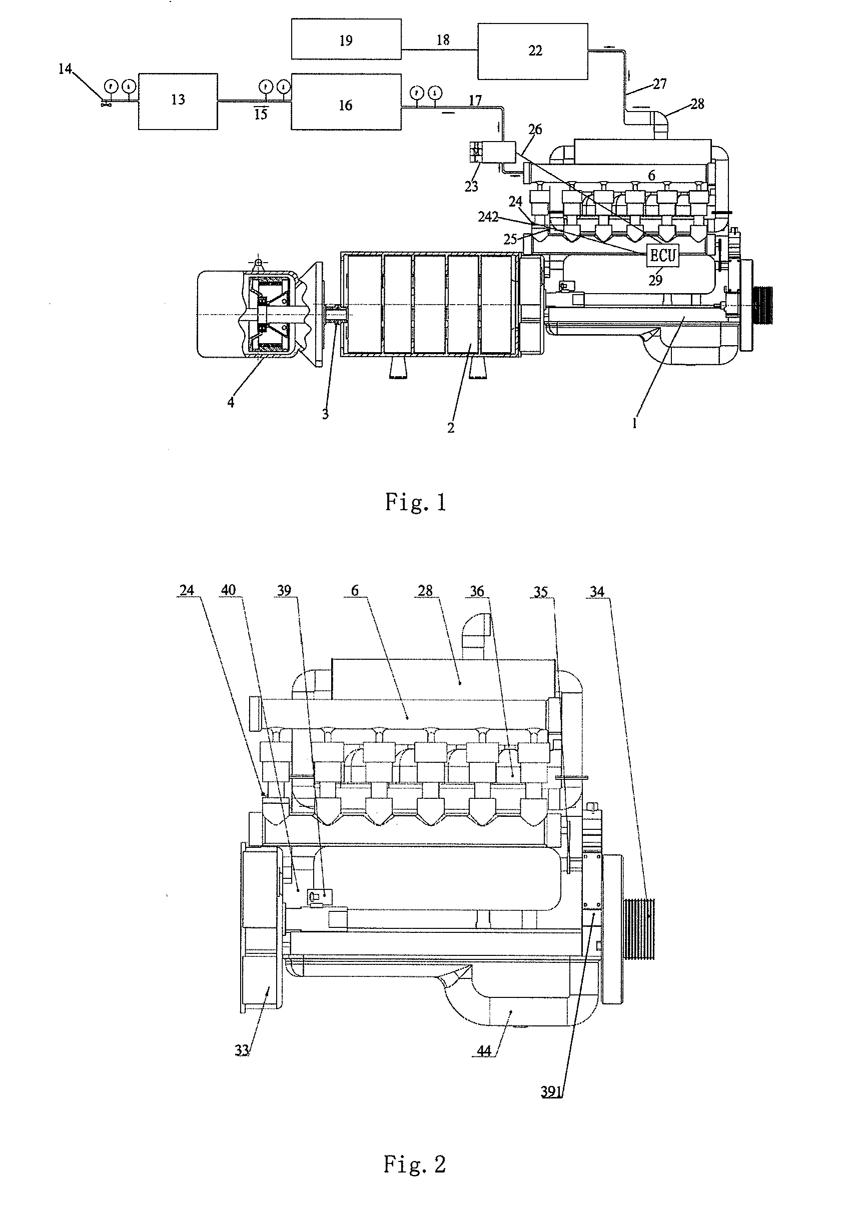
[0048]Now referring to FIG. 1, FIG. 1 is an overall schematic view of a two-stroke air-powered engine assembly in accordance with the present invention. Arrows in the figure show the flow direction of the air flow. In FIG. 1, the air-powered engine assembly includes an engine body 1, a multiple-column power distributor 2, a power equipment 4, a controller system 6, an air compressor 7, a condenser 11, an exhaust gas recycle tank 9, a high pressure gas tank set 13, a constant pressure tank 16, an intake speed control valve 23, an electro-drive turbine unidirectional suction pump 19, an electronic control unit ECU 29 and an impeller generator 22. As shown in FIG. 1, the high pressure air tank set 13 is connected ...


PUM


Abstract

A two-stroke air-powered engine assembly uses compressed air as a power source. The two-stroke air-powered engine includes an engine body (1), a multiple-column power distributor (2), a power equipment (4), a controller system (6), an intake speed control valve (23), a high pressure gas tank set (13), a constant pressure tank (16), and an electronic control unit ECO (29).

Description

TECHNICAL FIELD[0001]The invention relates to a two-stroke engine, and more particularly relates to a two-stroke air-powered engine assembly which uses compressed air as a power source.BACKGROUND[0002]The engine is widely used in all walks of life. It is commonly used as an internal combustion piston engine utilizing a fuel as the power source in the modern means of transport such as cars, boats, etc. The engine utilizing fuel as the power source would discharge gas with many harmful substances to pollute the environment because of insufficient fuel combustion on one hand, and on the other hand, the fuel is extracted from petroleum, and the development and utilization of the system using the fuel engine as the power source are increasingly limited by the increasing lack of the petroleum source. So an impending problem is to develop a new, clean and pollution-free alternative energy source or decrease fuel consumption and emissions as far as possible. So the air-powered engine which ...

Claims


Application Information

Patent Timeline
IPC IPC(8): F02B75/02
CPCF02B2075/025F02B75/02F01B17/025F01B23/10F01B25/02F01B29/04
Inventor ZHOU, DENGRONGZHOU, JIAN
Owner BEIJING XIANGTIAN HUACHUANG AERODYNAMIC FORCE TECH RES INST
Why Eureka
Try Eureka