Dry etching apparatus and clamp therefor

a technology of clamping apparatus and clamping plate, which is applied in the direction of electrical apparatus, basic electric elements, electric discharge tubes, etc., can solve the problems of resist mask adhering to the clamp, abnormal electrical discharge in the gap between the clamp and the stage, damage to the substrate, etc., to prevent the adhesion of the resist mask

Inactive Publication Date: 2014-08-14
FUJIFILM CORP
View PDF4 Cites 7 Cited by
  • Summary
  • Abstract
  • Description
  • Claims
  • Application Information

AI Technical Summary

Benefits of technology

[0039]According to the present invention, it is possible to prevent the resist mask from adhering to the clamp. It is

Problems solved by technology

Accordingly, the dry etching apparatus has the problem that a resist on the substrate adheres (sticks) to the clamp.
This can be a cause for damage to the substrate, such as the delamination of the resist film, and the generation of particles.
In add

Method used


Image

  • Dry etching apparatus and clamp therefor
  • Dry etching apparatus and clamp therefor
  • Dry etching apparatus and clamp therefor

Examples


Embodiment Construction

[0048]Hereinafter, embodiments of the present invention will be described in detail according to the accompanying drawings.

[0049]

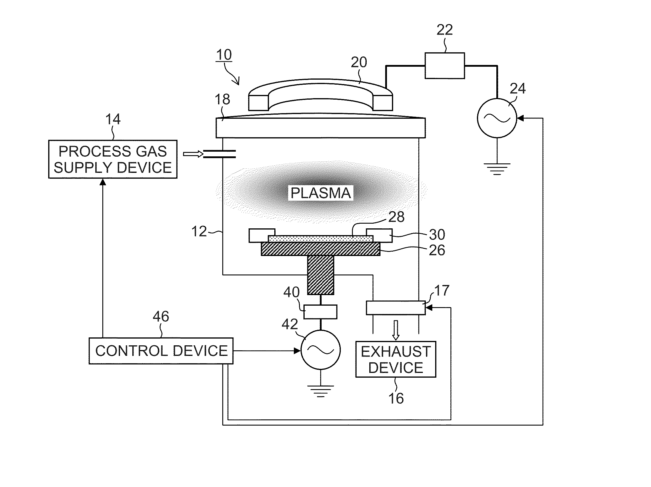
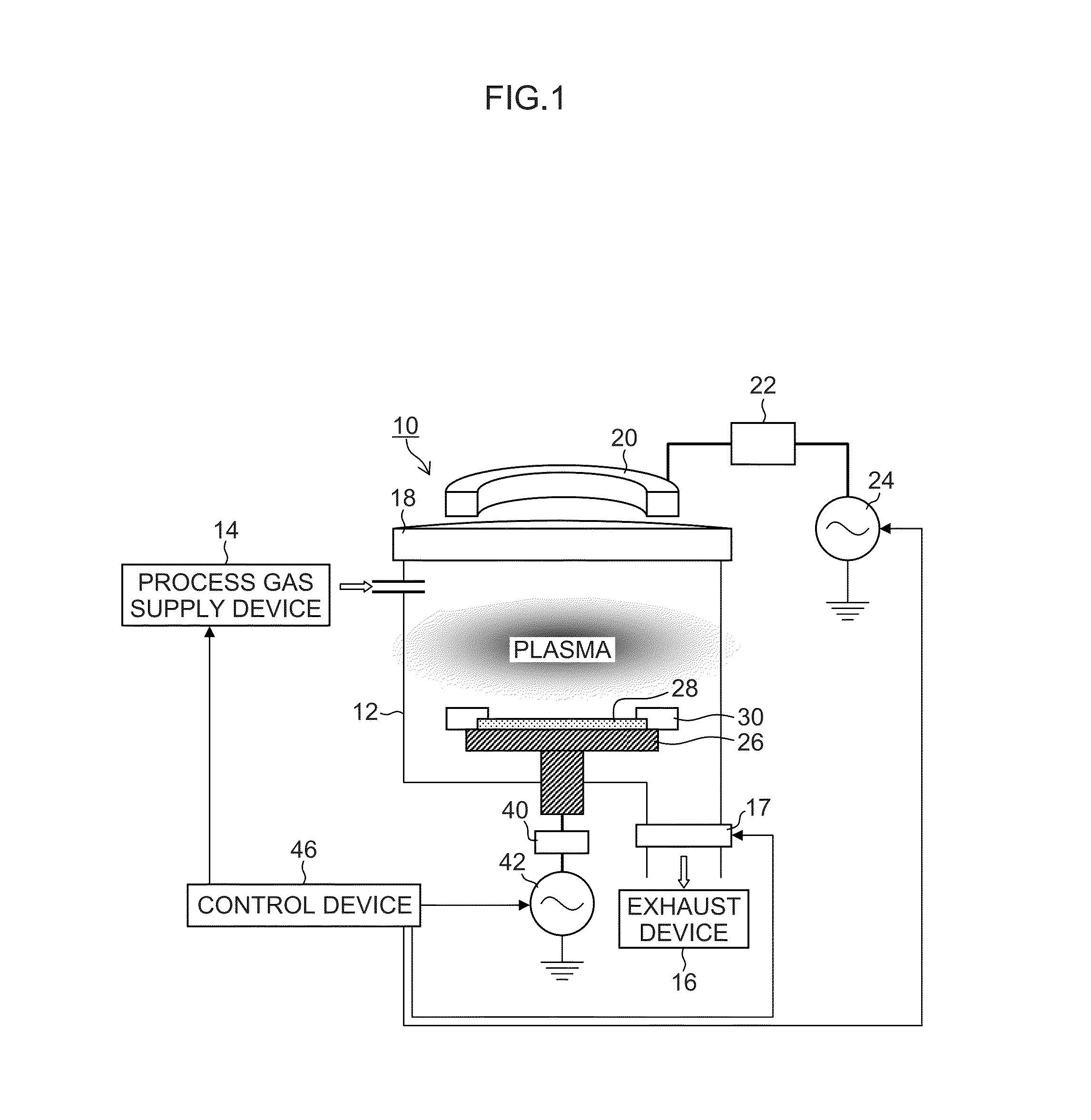
[0050]FIG. 1 is a drawing illustrating a schematic configuration of a dry etching apparatus according to an embodiment of the present invention. Here, a description will be made by citing, as an example, an apparatus used for the dry etching of silicon. A dry etching apparatus 10 illustrated in FIG. 1 is of the type in which inductively-coupled plasma (Induction Coupling Plasma: ICP) is applied. The dry etching apparatus is not limited to this type, however. When carrying out the present invention, it is also possible to use a dry etching apparatus in which a method using a source of plasma, such as helicon wave-excited plasma (Helicon Wave Plasma: HWP), electron cyclotron resonance plasma (ECP), or microwave-excited surface-wave plasma (Surface Wave Plasma: SWP) is used is applied.

[0051]The dry etching apparatus 10 is provided with a process gas supply de...


PUM

PropertyMeasurementUnit
Lengthaaaaaaaaaa
Thicknessaaaaaaaaaa
Adhesion strengthaaaaaaaaaa

Abstract

A dry etching apparatus according to an aspect of the present invention is provided with a stage on which a substrate including a resist mask on an outermost layer thereof is mounted; a clamp for holding down the substrate from above the resist mask to fix the substrate on the stage; a chamber within which the stage and the clamp are housed; an exhaust device which evacuates the chamber; a process gas supply device which supplies a process gas into the chamber; and a power supply for supplying electrical power used to generate plasma within the chamber, wherein the clamp has an annular structure for covering an entire outer circumference and side surface of the substrate, and an antiadhesion layer composed of an inorganic film for preventing an adhesion of a resist material is formed on the contact surface side of the clamp in contact with the substrate.

Description

BACKGROUND OF THE INVENTION[0001]1. Field of the Invention[0002]The present invention relates to a dry etching apparatus and a clamp for the dry etching apparatus, and particularly, to the structure of the clamp for fixing a substrate on a stage inside a chamber and a dry etching apparatus using the clamp.[0003]2. Description of the Related Art[0004]As a device which fixes a substrate (for example, a silicon wafer) on a stage in a dry etching apparatus used to manufacture semiconductor devices, MEMS (Micro-Electro-Mechanical System) devices, and the like, a configuration in which the peripheral part of the substrate is press-fixed with a clamp is known (see Japanese Patent Application Laid-Open No. 2002-299422). The invention described in Japanese Patent Application Laid-Open No. 2002-299422 proposes a wafer-fixing clamp for preventing adhesion between the wafer and a part of the clamp pressed on the wafer caused when the wafer press-fixed with the clamp is detached therefrom after ...

Claims


Application Information

Patent Timeline
IPC IPC(8): H01L21/687H01J37/20
CPCH01J37/20H01L21/687H01L21/68721H01J37/32082H01J37/32715
Inventor TAKAHASHI, SHUJI
Owner FUJIFILM CORP
Why Eureka
Try Eureka