
Working method for a system for partial mirroring of glass tubes, and said system

Inactive Publication Date: 2014-08-14
ABENGOA SOLAR NEW TECH SA
View PDF1 Cites 6 Cited by
  • Summary
  • Abstract
  • Description
  • Claims
  • Application Information

AI Technical Summary

Benefits of technology

The technical effect of this patent is the inclusion of a reflective layer on a glass tube of a solar collector. This reflective layer improves the efficiency of the collector by redirecting concentrated solar rays towards the absorbent tube. The reflective surface is integrated to the absorbent tube, forming a secondary reconcentrator and increasing the amount of solar energy absorbed. This results in the improvement of the solar plant's efficiency.

Problems solved by technology

There are several types of technologies for thermal-solar plants using receiving tubes, however, in all of them, collecting solar energy and its concentration is one of the greatest challenges.
Due to the foregoing, the partial mirroring of a glass tube to form the secondary reconcentrator becomes a critical problem that needs to be solved.
The use of this technique in our application becomes problematic because, since the secondary reconcentrator is found near the absorbent tube, the adhesives would reach temperatures nearing 100° C. and would degrade and lose their functionality.
Therefore, the reflective surfaces formed by films adhered to the glass would not have the optical quality required by this type of applications.
Current mirroring techniques, such as the one described in patent WO 2006 / 121516 A1, by means of spray, present problems for the partial mirroring of a glass tube due to the fact that, in general, the entire surface of the substrate to be mirrored would be covered by the reflective layer, thus wasting the metal, which is normally silver, copper or aluminum.
Electrolytic techniques, such as, for example, sputtering and vapor deposition techniques, are expensive, require vacuum, an external source of power and the use of ultra-pure metals, as described in U.S. Pat. No. 4,579,107 A of David Deakin.
These techniques use very expensive equipment which entail a very high initial investment.
Sputtering and vapor deposition techniques present difficulties in covering the interior of a tube with larger dimensions than the ones established above, since they would need to create a very large magnetic field and in addition, do not allow a partial mirroring because the metal is necessarily deposited around the 360 degrees of its perimeter and are too expensive to be practical.
The advantages of the technical simplicity of immersion or wetting for the mirroring of a glass tube do not compensate the numerous disadvantages presented by this technique, including the instability of the deposition baths when adding metal particles that remain in suspension, the 20 pm thickness per hour-limitation of the kinetics of the deposition and the limited adherence of the deposited metal layer.
Thermal sprays, although effective for solar cells, are ineffective for glass tubes because the temperature of the blown powder applied by the spray at high temperatures would degrade or break the glass tube.
Metallic layer protections are not valid for the mirroring of the internal surface of a glass tube since they should be deposited prior to the reflective layer.
Simply changing the order of deposition of the layers would not solve the problem either because it would decrease the optical quality of the reflective layer due to the roughness introduced by the metal layers; therefore, it could cause the reconcentrator to divert the rays from the desired focus thus losing its functionality.
In turn, this method would not allow the partial mirroring of a glass tube because the entire surface of the substrate to be mirrored is covered by the metal layers, thus wasting the metal, which is normally silver, copper or aluminum.

Method used

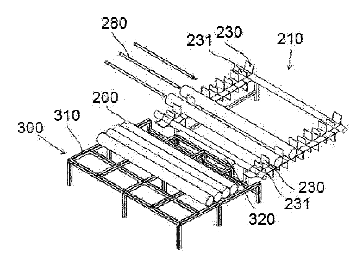
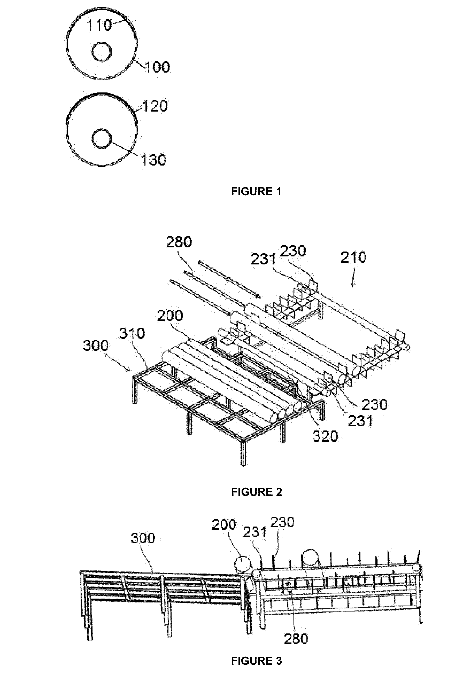
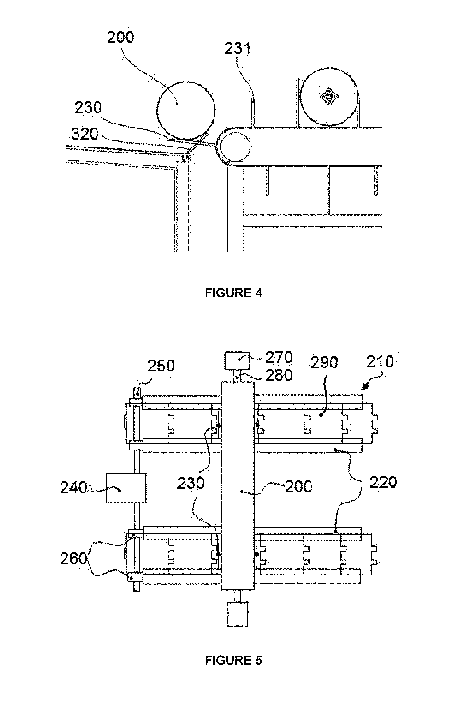

Image

  • Working method for a system for partial mirroring of glass tubes, and said system
  • Working method for a system for partial mirroring of glass tubes, and said system
  • Working method for a system for partial mirroring of glass tubes, and said system

Examples


Embodiment Construction

[0014]The present invention relates to a working method for a system for mirroring for glass tubes for the application of a reflective metal layer by means of chemical spray deposition on the internal and / or external surface of the tube.

[0015]As commented above, the main application to be given to the tube is to be used as the external tube of a solar collector receiver incorporating a secondary reconcentrator. The reflective layer of the mirror with which part of the tube is desired to be coated is the secondary reconcentrator.

[0016]Taking into account the function to be performed by the tube, the reflective layer is to be deposited along the glass tube and only in the middle or part of the perimeter of the tube. The entire tube is not mirrored to allow the entry of solar rays through the non-mirrored surface. The reflective surface reflects the concentrated incident solar rays and redirects them towards the absorbent tube so that it absorbs a larger amount of concentrated rays, di...


PUM

PropertyMeasurementUnit
Temperatureaaaaaaaaaa
Fractionaaaaaaaaaa

Abstract

Working method for a system for partial mirroring of glass tubes and said system, made up by an tube supply facility, a chain where the mirroring is carried out in different fixed stations and a tube output facility, in which the main partial mirroring steps are the following:cleaning the glass tubesensitizing the surfacewashingoptional activation or super-sensitization stepwashingplatingwashingdryingin the case of external partial mirroring, the following steps are added:depositing the copper layerwashingdepositing anti-corrosion paintdepositing mechanical and UV protective paintcuring the paintexternal drying of the tube

Description

TECHNICAL FIELD OF THE INVENTION[0001]The invention belongs to the field of metal coatings of glass surfaces, more specifically, it relates to the non-electrolytic mirroring of a glass tube by spray.[0002]This glass tube can be a part of a receiving tube for a solar collector.BACKGROUND OF THE INVENTION[0003]The main principle of the thermal-solar technology is based on the concept of the concentration of solar radiation to heat a heat-carrying fluid and generate electricity. Said heat-carrying fluid circulates through the interior of an absorbent tube, generally metallic, introduced into a glass tube, thus creating vacuum among them which decreases thermal losses. The set of both tubes is known as receiving tube.[0004]There are several types of technologies for thermal-solar plants using receiving tubes, however, in all of them, collecting solar energy and its concentration is one of the greatest challenges.[0005]In order to increase both aspects, different solutions (optical, inno...

Claims


Application Information

Patent Timeline
IPC IPC(8): C03C17/10
CPCB65G17/14B65G49/02B65G49/05C03C17/003C03C17/3663C03C17/38F24J2/055F24J2002/1071C03C17/10C03C2217/70C03C2218/31C03C2218/32Y02E10/44F24S10/45F24S2023/86
Inventor NUNEZ BOOTELLO, JUAN PABLOGOMEZ RUIZ, EDUARDO
Owner ABENGOA SOLAR NEW TECH SA
Learn More