Photoreactor and Process for Preparing MIP Nanoparticles

a photoreactor and nanoparticle technology, applied in the field of photoreactors, can solve the problems of difficult recovery, frequent need to use templates which are expensive and/or difficult to obtain, and the inability to use molecularly imprinted polymers (mips) in pharmacology and medicin

Inactive Publication Date: 2014-08-14
MIP DIAGNOSTICS LTD
View PDF2 Cites 8 Cited by
  • Summary
  • Abstract
  • Description
  • Claims
  • Application Information

AI Technical Summary

Benefits of technology

[0034](iv) causing the radiation source to irradiate the vessel's interior to effect controlled polymerisation of the polymerisable composition, while using the cooler / heater to control the temperature thereof;

Problems solved by technology

Because of their inherent insolubility, the possibility to use molecularly imprinted polymers (MIPs) in pharmacology and medicine is restricted.
One of the complications in MIP synthesis is the frequent need to use templates which are expensive and / or difficult to obtain, such as proteins, some toxins etc.
Such templates are also difficult to recover after polymerisation and limit the amount of MIP that can be obtained.
In all of the examples disclosed in U.S. Pat. No. 7,393,909, the surface bearing the immobilised template is lost during the dissolution process and cannot be re-used.
Potentially the template-bearing surfaces disclosed in these reports can be regenerated and used several more times. These approaches can be used for the production of sensors or arrays, but would be difficult to adapt for the production of nanoparticles or small soluble molecules.
Yet another major problem associated with MIPs is heterogeneity of the binding sites produced, which is generally responsible for high levels of non-specific binding.

Method used


Image

  • Photoreactor and Process for Preparing MIP Nanoparticles
  • Photoreactor and Process for Preparing MIP Nanoparticles

Examples


example 1

[0073]Preparation of template-derivatised solid support.

[0074]Glass beads were activated by boiling in NaOH 4 M for 10 minutes, then washed with double-distilled water and acetone and dried at 80° C. The beads were then incubated in a 2% v / v solution of 3-aminopropyl trimethoxysilane in toluene overnight, washed with acetone and subsequently incubated in a 7% v / v solution of glutaraldehyde in PBS buffer pH 7.2 for 2 hours, after which they were rinsed with double-distilled water. The surface immobilisation of the template was performed by incubating the heads in a 5 mg / ml solution of the template in PBS pH 7.2 overnight at 4° C. Methylpyrrolidone (10% v / v) was also added as co-solvent during the immobilisation of melamine. The glass beads were washed with water and dried under vacuum, then stored at 4° C. until use.

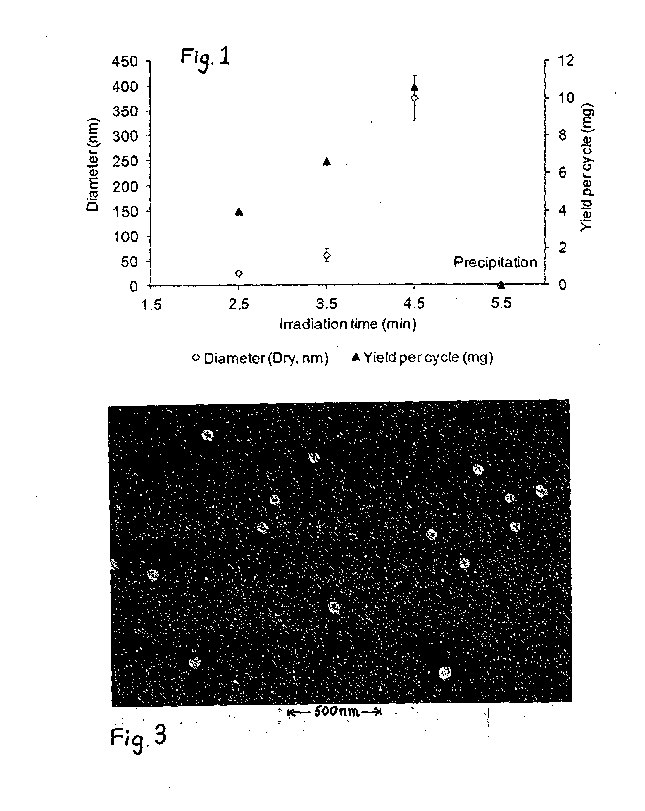
Automated synthesis of imprinted particles with specificity towards melamine.

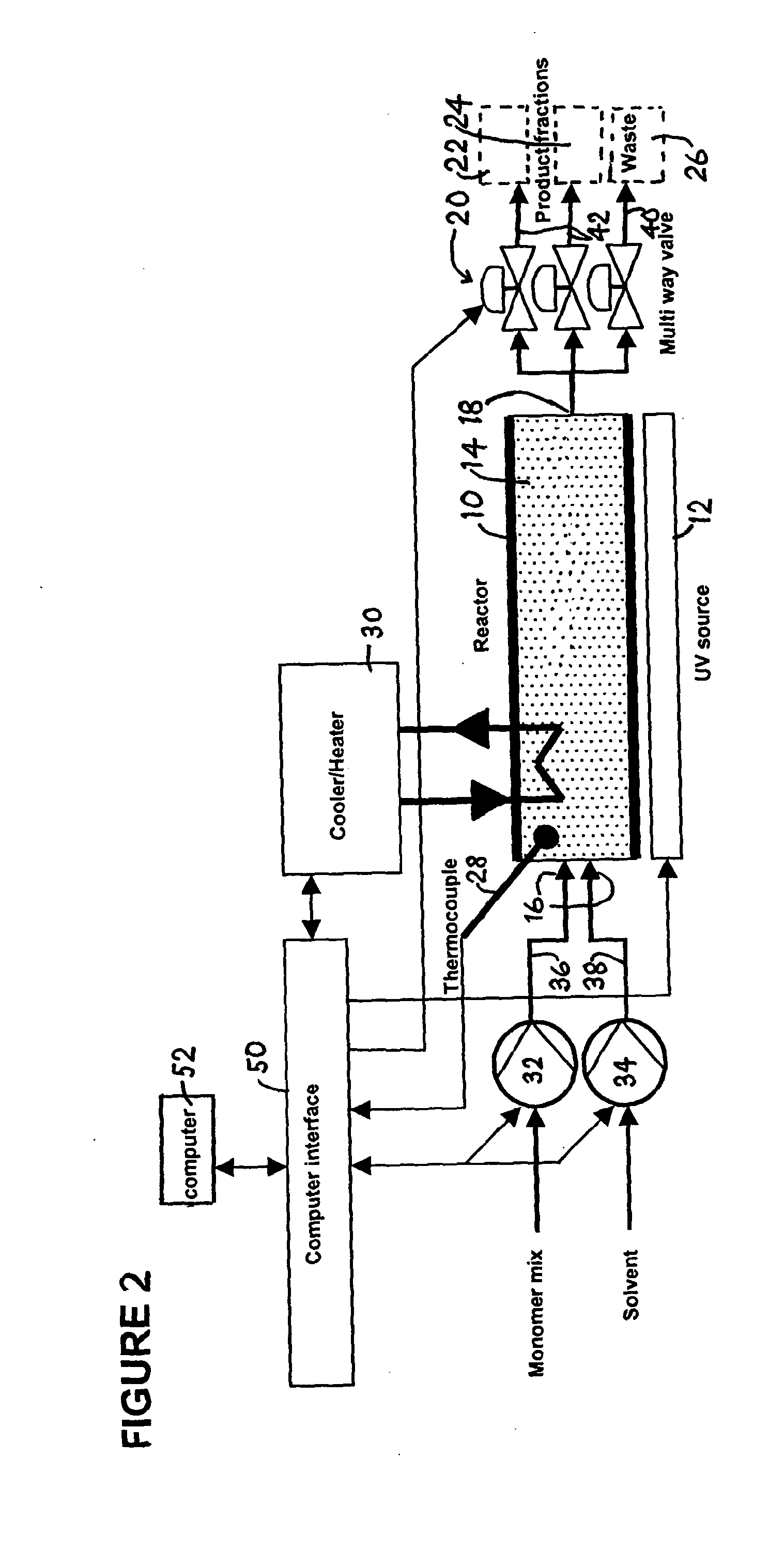
[0075]The synthesiser used consisted of two pumps 32, 34 delivering up to eight separate feed...

example 2

[0076]Automated synthesis of imprinted particles with specificity towards vancomycin.

[0077]For the synthesis of imprinted polymer particles, glass beads (23.5 g) coated with vancomycin were prepared generally as described in Example 1, and loaded into the temperature controlled glass reactor. The setup used was as described in Example 1. The following steps were all programmed into the control software and the synthesiser operated in automatic mode. The reactor was filled with solvent (acetonitrile) delivered by a computer-controlled pump. The column was cooled down to 4° C. and 4 ml of monomer mixture injected onto the column from a different feed line. The composition of the monomer mixture was (in % w / w): Acetonitrile 79%, N-isopropylacrylamide (NIPAm) 10%, N-tert-butylacrylamide (TBAm) 8.5%, benzyl diethyldithiocarbamate (INIFERTER) 1.62%, N,N′-methylenebisacrylamide (BIS) 0.5%. The polymerisation was initiated by UV irradiation which lasted 3.5 min. Afterwards the solvent pump ...


PUM

PropertyMeasurementUnit
molecular weightsaaaaaaaaaa
diametersaaaaaaaaaa
diameteraaaaaaaaaa

Abstract

Soluble or colloidal nanoparticles of molecularly imprinted polymer are produced reliably and consistently in a photoreactor with a reaction vessel (18) containing a solid phase (14) bearing immobilised template. Parameters such as temperature, fluid flows and irradiation time are controlled by a computer (52).

Description

TECHNICAL FIELD [0001]The present invention relates to novel processes and equipment for producing nanoparticles made at molecularly imprinted polymers.BACKGROUND ART [0002]The term “template-directed synthesis” includes the formation of a new substance by chemical modification of a substrate, or by the coupling of two or more molecules, in the presence of a template which serves as a pattern for new structure formation. A specific example is “molecular imprinting”, based on the polymerisation of vinyl or acrylic monomers in the presence of a template or templates (see ref. 1, 2). The traditional approach involves the production of highly cross-linked imprinted polymers, which are insoluble in aqueous and organic solvents. Because of their inherent insolubility, the possibility to use molecularly imprinted polymers (MIPs) in pharmacology and medicine is restricted. Recently, several attempts have been made to develop protocols for the preparation of imprinted polymers with relativel...

Claims


Application Information

Patent Timeline
Patent Type & Authority Applications(United States)
IPC IPC(8): C08F2/48B01J19/12
CPCC08F2/48B01J19/123B01J2219/1203B01J2219/0801B01J2219/0877B01J4/008B01J8/065B01J19/127B01J20/268B01J20/28007B01J2208/00061B01J2208/00203B01J2208/00424B82Y30/00C08F293/005C08J5/18C08J9/26
Inventor PILETSKY, SERGEYPILETSKA, OLENAGUERREIRO, ANTONIOWHITCOMBE, MICHAELPOMA, ALESSANDRO
Owner MIP DIAGNOSTICS LTD
Why Eureka
Try Eureka