Slide Scanner with a Tilted Image

Active Publication Date: 2014-08-21
HURON TECH INT
View PDF1 Cites 16 Cited by
  • Summary
  • Abstract
  • Description
  • Claims
  • Application Information

AI Technical Summary

Benefits of technology

This patent describes a method and instrument for scanning large microscopic specimens on glass slides using a linear detector array that can be tilted during scanning to maintain focus across the entire width of the scan strip. The instrument and method can also be used for fluorescence imaging and 2D detector arrays. Additionally, the patent explains how to measure the focus and tilt needed to maintain focus during scanning. The technical effect is to provide a more efficient and accurate way to scan and analyze large microscopic specimens.

Problems solved by technology

Such images may contain tiling artifacts caused by different focus positions for adjacent tiles.
For large specimens, thousands of tiles may be required to image the entire specimen, requiring many changes in focus which increase the chances of tiling artifacts.
When a CCD-based TDI array is used, each line image stored in memory is the result of integrating the charge generated in all of the previous lines of the array while the scan proceeds, and thus has both increased signal / noise and amplitude (due to increased exposure time) when compared to the result if a linear array detector were used.
If the specimen is not flat, or the specimen is tilted about the scan direction, proper focus may not be achieved across the whole width of the strip.
In addition, focus at the edge of adjacent strips may be different, making it difficult to stitch image strips together to assemble a complete image of the specimen without focus mismatch at the edge of strips.
These problems are made worse when magnification is increased (which decreases depth of field) and when the width of the scan strip on the specimen is increased.

Method used


Image

  • Slide Scanner with a Tilted Image
  • Slide Scanner with a Tilted Image
  • Slide Scanner with a Tilted Image

Examples


second embodiment

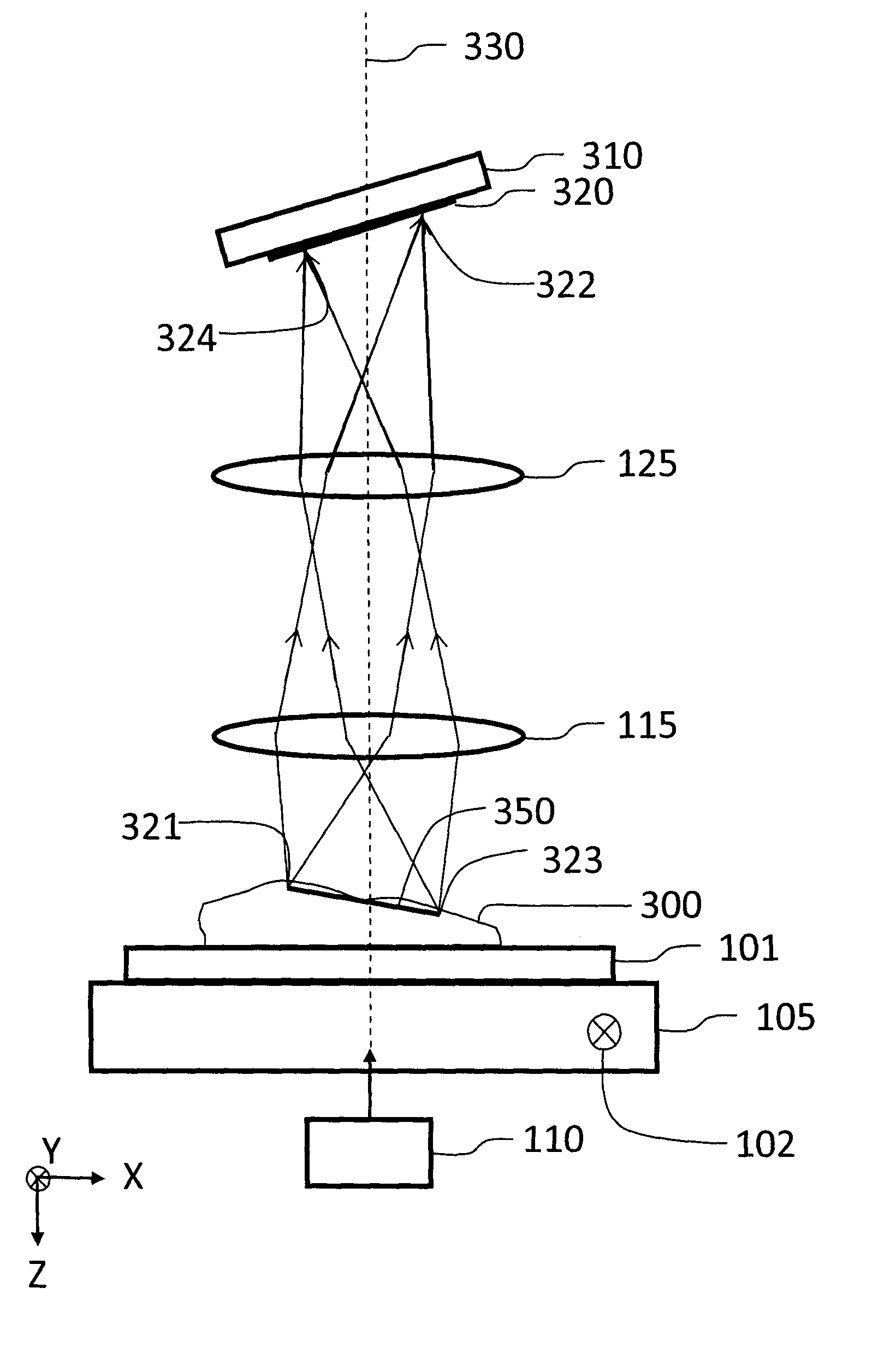
[0032]FIG. 4 shows a slide scanner 450 for transmission imaging that is this invention. A tissue specimen 400 (or other specimen to be imaged) mounted on microscope slide 401 is illuminated from below by illumination source 110. Light passing through the specimen is collected by infinity-corrected microscope objective 115 which is focused on the specimen by piezo positioner 120 (or other focusing mechanism). The microscope objective 115 and tube lens 125 form a real image of the specimen on linear detector array 425, which can be tilted about tilt axis 430 using piezoelectric pusher 420 (or other tilt mechanism). The long dimension of linear detector array 425 is perpendicular to scan direction 102. Tilt axis 430 is parallel to scan direction 102. An image of the specimen is collected by moving the microscope slide at constant speed using motorized stage 405 in a direction perpendicular to the long dimension of the detector array 425, combining a sequence of equally-spaced line imag...

fourth embodiment

[0038]In FIG. 5, if TDI detector array 525 is replaced by an ordinary two-dimensional (2D) detector array (not a TDI array), then Moving Specimen Image Averaging can be used to acquire fluorescence image strips as described above. This is this invention. Both focus position and tilt can be measured by performing a Z-scan at several Y positions along each strip before scanning, with the detector tilt set at zero. With the detector parallel to the scan plane, a Z-scan can be performed by moving the microscope objective in the Z direction using the piezo positioner to a series of equally-spaced positions in Z, while storing the resulting series of 2D images, each of which has the same width as the scan strip, using the 2D detector (or alternatively, a Z-scan can be performed by moving either the detector or the specimen in the Z direction). This results in a 3D image stack at each Y position, and if the detector used as an example in the description above is used, this image stack cont...


PUM


Abstract

An instrument and method for scanning a large microscope specimen uses a light source and at least one lens to focus light from the specimen onto a detector array. The specimen holder is located on a scanning stage and the detector array is dynamically tilted about a scan direction during the scan to maintain focus across the width of the scan strip as the scan proceeds. A degree of tilt varies during the scan as is required to maintain lateral focus relative to the detector array.

Description

BACKGROUND OF THE INVENTION[0001]1. Field of the Invention[0002]This invention relates to the fields of microscopic imaging of large specimens with particular emphasis on brightfield and fluorescence imaging. Applications include imaging tissue specimens, genetic microarrays, protein arrays, tissue arrays, cells and cell populations, biochips, arrays of biomolecules, detection of nanoparticles, photoluminescence imaging of semiconductor materials and devices, and many others.[0003]2. Description of the Prior Art[0004]Several technologies are used for imaging large specimens at high resolution. Tiling microscopes record an image of a small area of the specimen using a digital camera (usually a CCD camera), the specimen is moved with a computer-controlled microscope stage to image an adjacent area, an image of the adjacent area is recorded, the stage is moved again to the next area, and so on until a number of image tiles have been recorded that together cover the whole area of the sp...

Claims


Application Information

Patent Timeline
IPC IPC(8): G02B21/00G02B21/06G02B21/16
CPCG02B21/002G02B21/06G02B21/16B82Y35/00G01N21/6456G02B21/34G02B21/367
Inventor DAMASKINOS, SAVVASDIXON, ARTHUR EDWARD
Owner HURON TECH INT
Why Eureka
Try Eureka