
MODELLING OF ToF-DOI DETECTOR ARRAYS

Active Publication Date: 2014-08-21
KONINKLJIJKE PHILIPS NV
View PDF1 Cites 15 Cited by
  • Summary
  • Abstract
  • Description
  • Claims
  • Application Information

AI Technical Summary

Benefits of technology

The invention provides a detector with improved timing and energy resolution using DOI encoding. By designing optical compartments and setting coupling parameters, a detector with individual focal spots in the flood map can be achieved. The detector array may include digital silicon photomultipliers and light guides for coupling the layers. The optical compartments may also provide reflectors in a specific direction to achieve desired DOI information. Overall, the invention allows for precise detection and flexible detector design.

Problems solved by technology

At every dynode stage the incident electrons have gained sufficient energy to create secondary electron emissions from collisions with the dynode, thus resulting in a large electron cloud at the anode.
In some of the earlier PET systems, gamma detectors could be used only to determine the location of gamma interaction with the detector in two dimensions, which gave rise to parallax errors.
More particularly, a conventional two-dimensional measurement of the spatial location of a detected gamma ray absorption event in the scintillating crystal is limited to a two-dimensional point in the X,Y plane of the crystal.
The paralax error is a key limiting factor in image resolution, especially for larger patients.
This reduces the detectability of small lesions in the outer field of view.
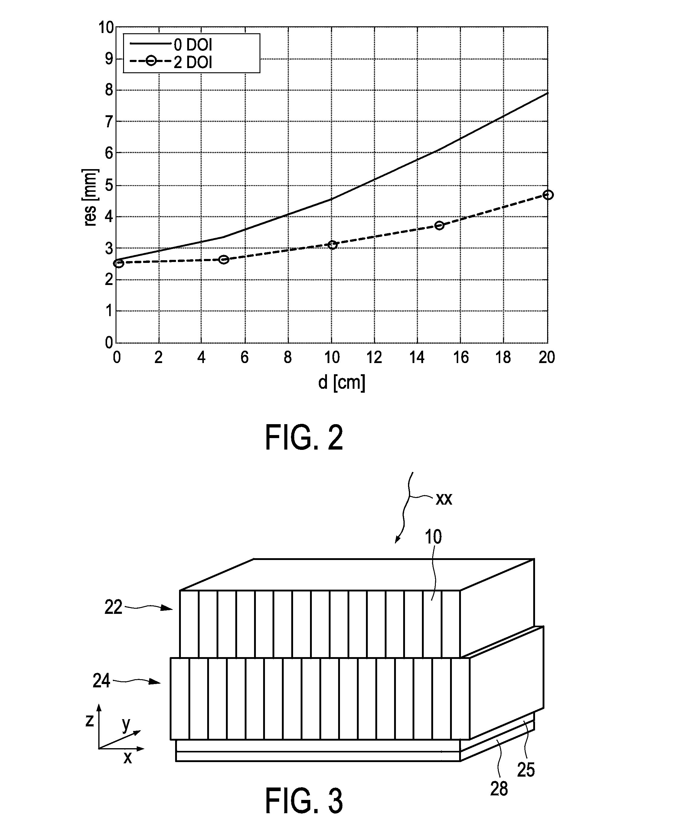
So far, conventional PET systems (“0 DOI”) suffer from DOI problems and the resolution deteriorates for larger objects across the axial field of view.
Therefore, lesions in the outer contour of the human body (especially large patients) like cancerous lymph nodes cannot be detected with the same image resolution as objects in the body centre.
However, such multi layer DOI encodings suffer from deterioration in timing resolution, as the light is spread over a larger area.
This is especially problematic for analog SiPM readout due to their much higher noise floor than photo multiplier tubes (PMTs), which is 1000-10000 times higher per unit area.
Therefore, excellent timing can only be achieved when a small sensitive area (at low sensor temperature) is used.

Method used


Image

  • MODELLING OF ToF-DOI DETECTOR ARRAYS
  • MODELLING OF ToF-DOI DETECTOR ARRAYS
  • MODELLING OF ToF-DOI DETECTOR ARRAYS

Examples


first embodiment

[0053]FIG. 5 shows a flood map (lower portion of FIG. 5) and top (T) and side (S) views of a first setup (A) of a DOI detector device with DOI encoding. The measurement conditions included 2D encoding due to reflector foils in the outer layer, all crystals grinded on one outer side, inner layer (IL) with air gaps 21 without reflector, outer layer (OL) with reflectors 27 (in x and y direction), coupling by an optical coupling agent 26 (e.g. lightguide) of e.g. 25 μm thickness, and a single crystal of e.g. 10 mm as reference. Furthermore, a SiPM sensor 28 can be used as photo detector. As a result, a coincidence resolving time (CRT) of 325 ps+ / −20 ps, a light yield of approximately 1000 photons and an energy resolution of approximately 11% were obtained. Also several TDCs per sensor die reduce dark count triggers, as the light is shared only among two SiPMs (and not 4 SiPMs). This allows equal dark count triggers (or dead time) at higher effective operation temperature which is impor...

second embodiment

[0054]FIG. 6 shows a flood map and top (T) and side (S) views of a second setup (B) of a DOI detector device with DOI encoding. Here, the measurement conditions included 8 crystals of e.g. 3.8 mm*3.8 mm*10 mm per die, inner layer (IL) horizontal reflector, inner layer (IL) air gap 21, outer layer (OL) vertical reflector 27, optically coupled by a lightguide 26. Again, a SiPM sensor 28 can be used as photo detector.

[0055]As a result, a CRT of 340 ps+ / −20 ps, layer-independent light yield, and an energy resolution of approximately 11.5% was obtained.

[0056]The mounting complexity of the setup according to the second embodiment is comparable to the above first embodiment, but uses the asymmetry in vertical and horizontal spread to do the encoding. An extension to three-layer DOI is not possible here.

third embodiment

[0057]FIG. 7 shows a flood map and top (T) and side (S) views of a third setup (C) of a DOI detector device with DOI encoding. Here, the measurement conditions included 8 crystals of e.g. 3.8 mm*3.8 mm*10 mm per die, outer layer (OL) vertical reflectors 27, inner layer (IL) light guides 26, optically coupled by a horizontal lightguide 26. Again, a SiPM sensor 28 can be used as photo detector.


PUM


Abstract

The invention is directed to several crystal arrangements for time-of-flight (ToF) positron emission tomography (PET) with depth of interaction (DOI) encoding for high spatial, energy and timing resolution. Additionally, several implementations of the ToF-DOI PET detector arrays are proposed with related measurements which all show that no timing degradation is visible in the used setup for first photon trigger for digital silicon photo multipliers (dSiPMs).

Description

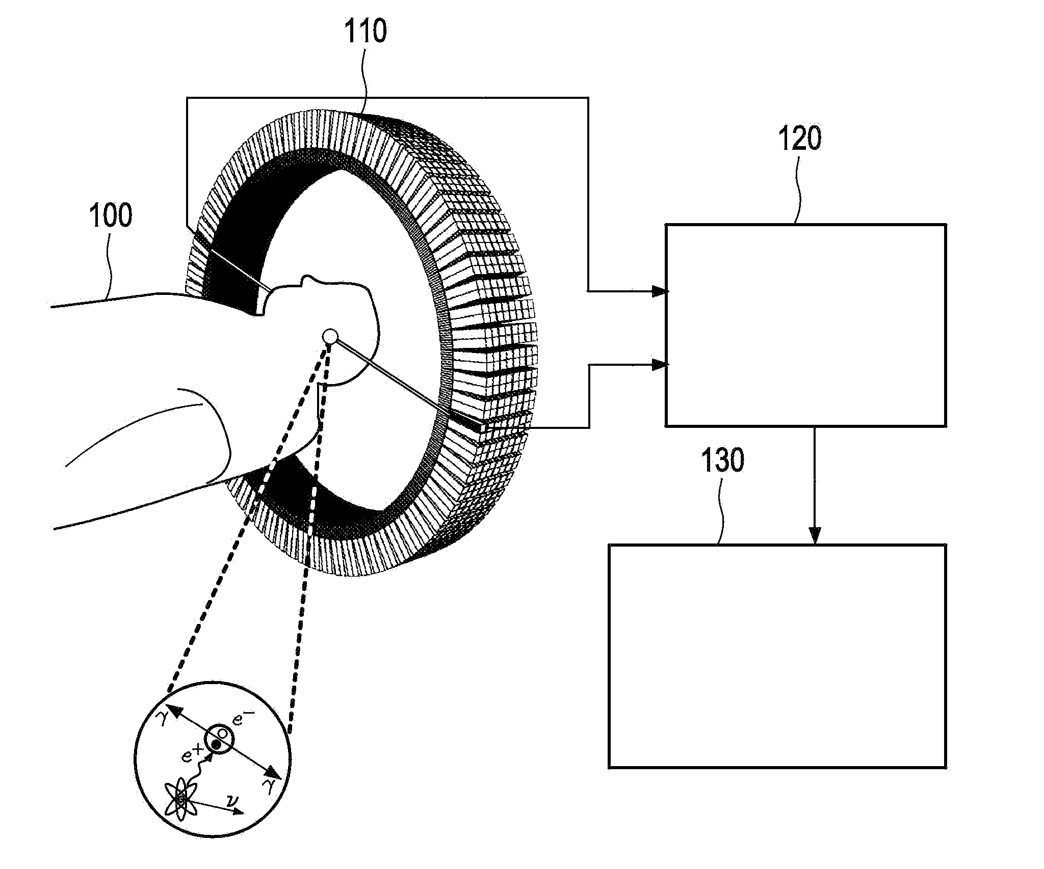
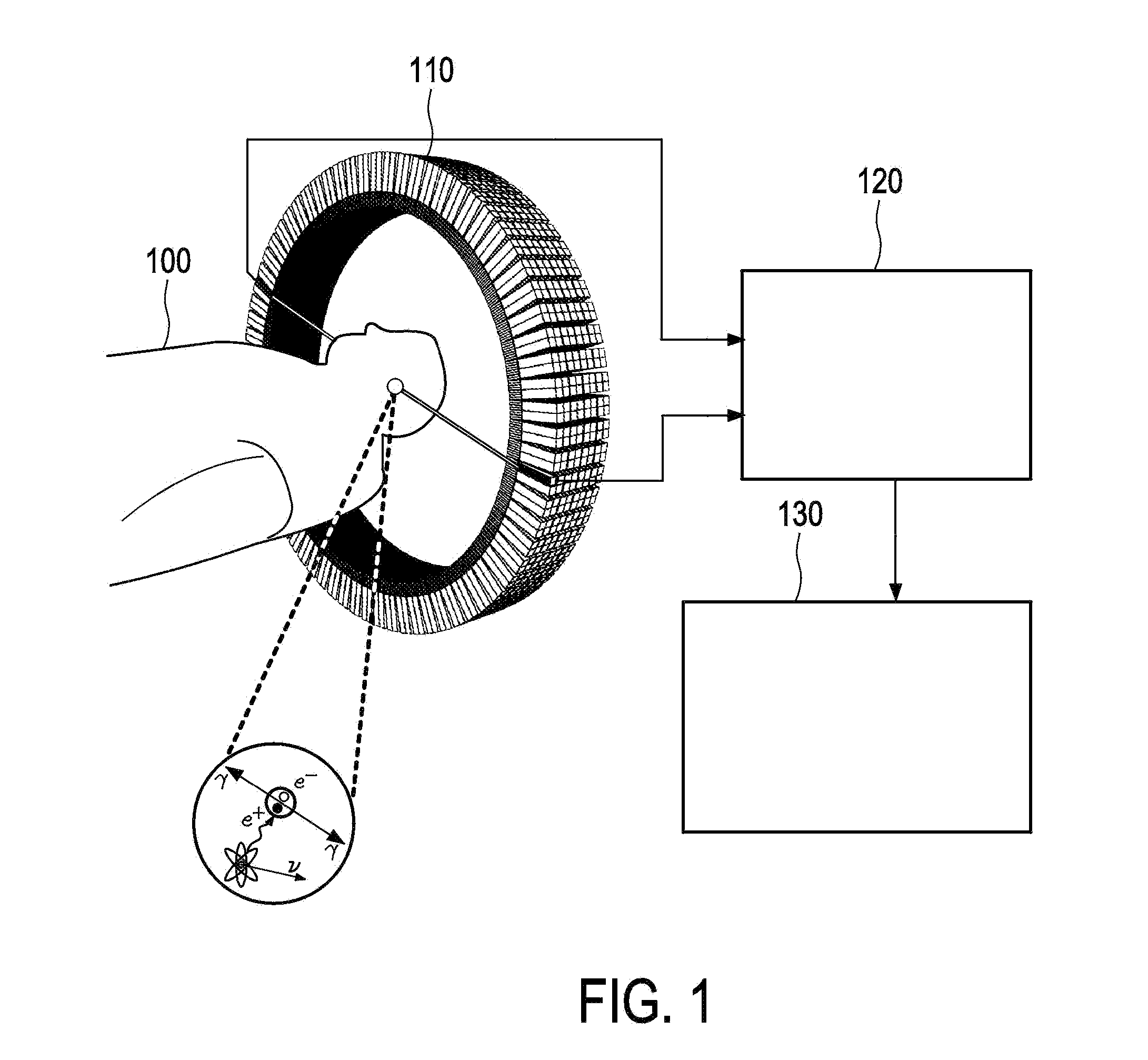
FIELD OF THE INVENTION[0001]The invention relates to the field of positron emission tomography (PET) systems with depth-of-interaction (DOI) and time-of-flight (ToF) encoding.BACKGROUND OF THE INVENTION[0002]Recent advances in the field of medical imaging have greatly facilitated the transition from technologies used to accurately image structures inside the human body to technologies sensitive enough to provide functional and biological information at the cellular and the molecular level. PET is considered to be one of the most sensitive in-vivo molecular imaging modalities despite its significantly inferior spatial resolution compared to imaging modalities such as computed tomography (CT) and magnetic resonance imaging (MRI). The improvement of PET detector technology is an active field of research and efforts are focused on addressing the limits in spatial resolution and sensitivity achieved in PET.[0003]FIG. 1 shows a schematic block diagram of a PET imaging system in which the ...

Claims


Application Information

Patent Timeline
IPC IPC(8): G01T1/20
CPCG01T1/2002G01T1/2985A61B6/037G01T1/20
Inventor DUEPPENBECKER, PETER MICHAEL JAKOBSOLF, TORSTEN
Owner KONINKLJIJKE PHILIPS NV
Learn More