Cover plate for wind mark control in spin coating process

a coating process and wind mark technology, applied in coatings, liquid surface applicators, instruments, etc., can solve problems such as wind marks, non-uniformity and/or defects in coatings, and defects in later processing steps, so as to reduce process time, improve throughput, and reduce the effect of process tim

Active Publication Date: 2014-08-21
TOKYO ELECTRON LTD
View PDF11 Cites 9 Cited by
  • Summary
  • Abstract
  • Description
  • Claims
  • Application Information

AI Technical Summary

Benefits of technology

[0005]A common desire in semiconductor manufacturing and spin coating is to have a high throughput. During semiconductor manufacturing, a wafer can undergo multiple coating and developing steps. Accordingly, minimizing process time to complete each spin coating of a wafer can improve throughput. In other words, it is desirable to complete a spin coat or spin process in as little time as possible to increase a number of wafers that can be processed per unit of time. One challenge with increasing throughput is meeting uniformity and quality requirements. In a typical spin coating process that uses rotation to both spread liquid material across the wafer, and to dry the liquid material, the drying time lasts substantially longer than the spreading time. There are various techniques that can be used to accelerate drying time. One basic technique is to increase a rotational speed of the wafer, which in turn increases a fluid-flow speed across the surface of the wafer—the faster the wafer spins, the faster a liquid resist or other liquid chemical dries (solvent evaporates).

Problems solved by technology

One challenge with increasing throughput is meeting uniformity and quality requirements.
Higher rotational speeds of the substrate, however, can result in non-uniformity and / or defects in the coating.
These defects are typically a result of turbulent air flow across the surface of the wafer triggered by relatively faster rotational velocities.
One specific problem of higher rotational speeds of the substrate is the development of wind marks, also known as Ekman spirals.
These patterns (wind marks) cause defects during later processing steps due to the lack of uniformity of the resist thickness.
This is especially challenging as the semiconductor industry transitions from processing wafers of 300 mm in diameter to wafers of 450 mm in diameter.
Such a reduction in speed has two significant challenges.
One challenge is that at such relatively lower rotational speeds, the liquid does not spread across the wafer surface as uniformly (lower centrifugal force).
Another challenge with the lower rotational speed is a dramatic increase in dry time.

Method used


Image

  • Cover plate for wind mark control in spin coating process
  • Cover plate for wind mark control in spin coating process
  • Cover plate for wind mark control in spin coating process

Examples


Embodiment Construction

[0026]For purposes of explanation and not limitation, the following description sets forth specific details, such as a particular geometry of a processing system, descriptions of various components and processes used therein. It should be understood, however, that the invention may be practiced in other embodiments that depart from these specific details.

[0027]Similarly, for purposes of explanation, specific numbers, materials, and configurations are set forth in order to provide a thorough understanding of the invention. Nevertheless, the invention may be practiced without specific details. Furthermore, it is understood that the various embodiments shown in the figures are illustrative representations and are not necessarily drawn to scale.

[0028]Various operations will be described as multiple discrete operations in turn, in a manner that is most helpful in understanding the invention. However, the order of description should not be construed as to imply that these operations are n...


PUM


Abstract

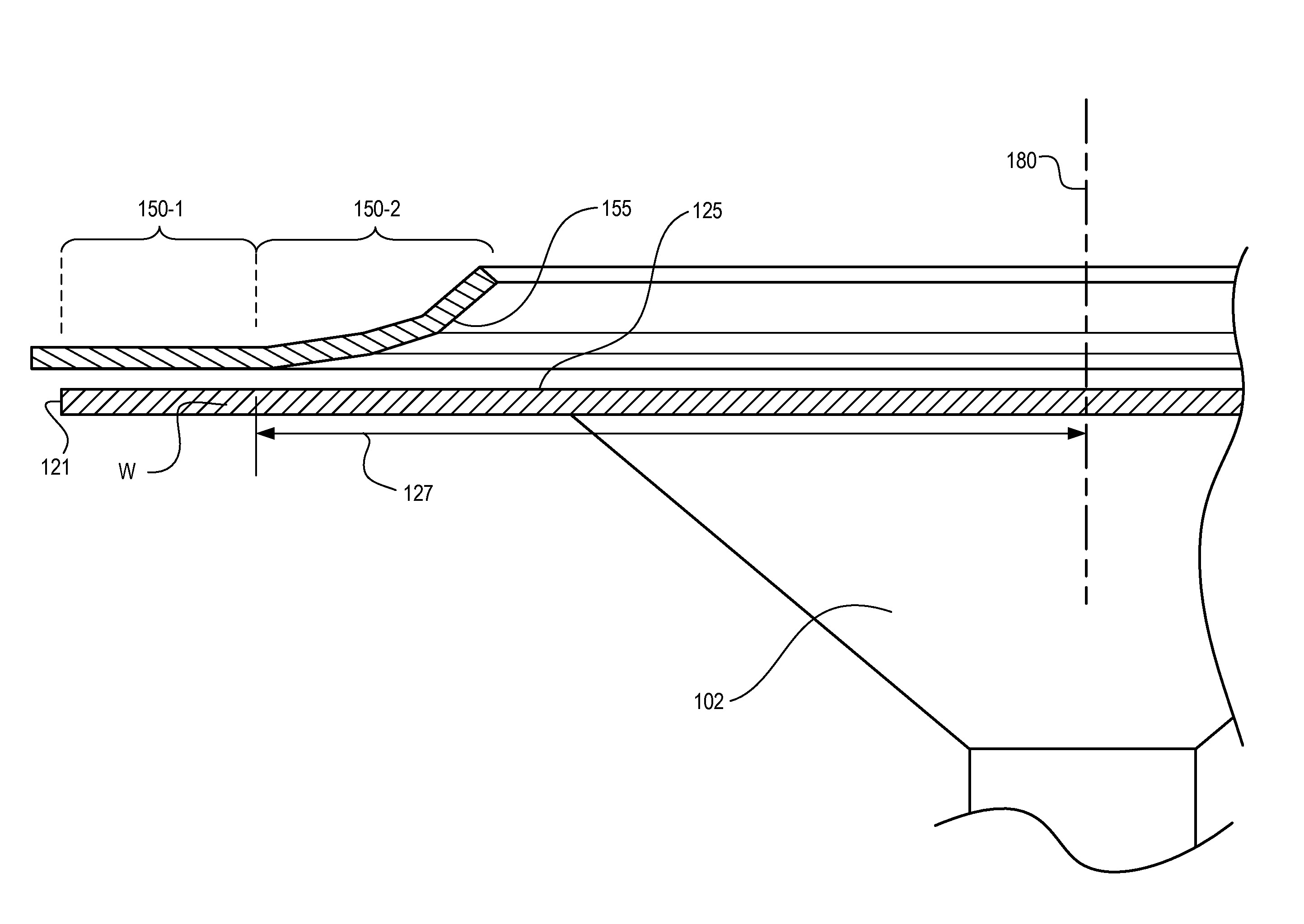
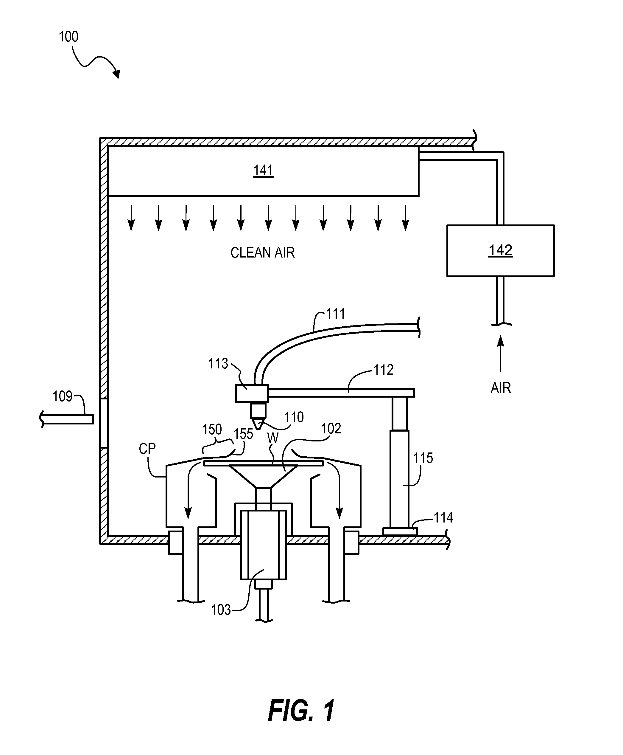
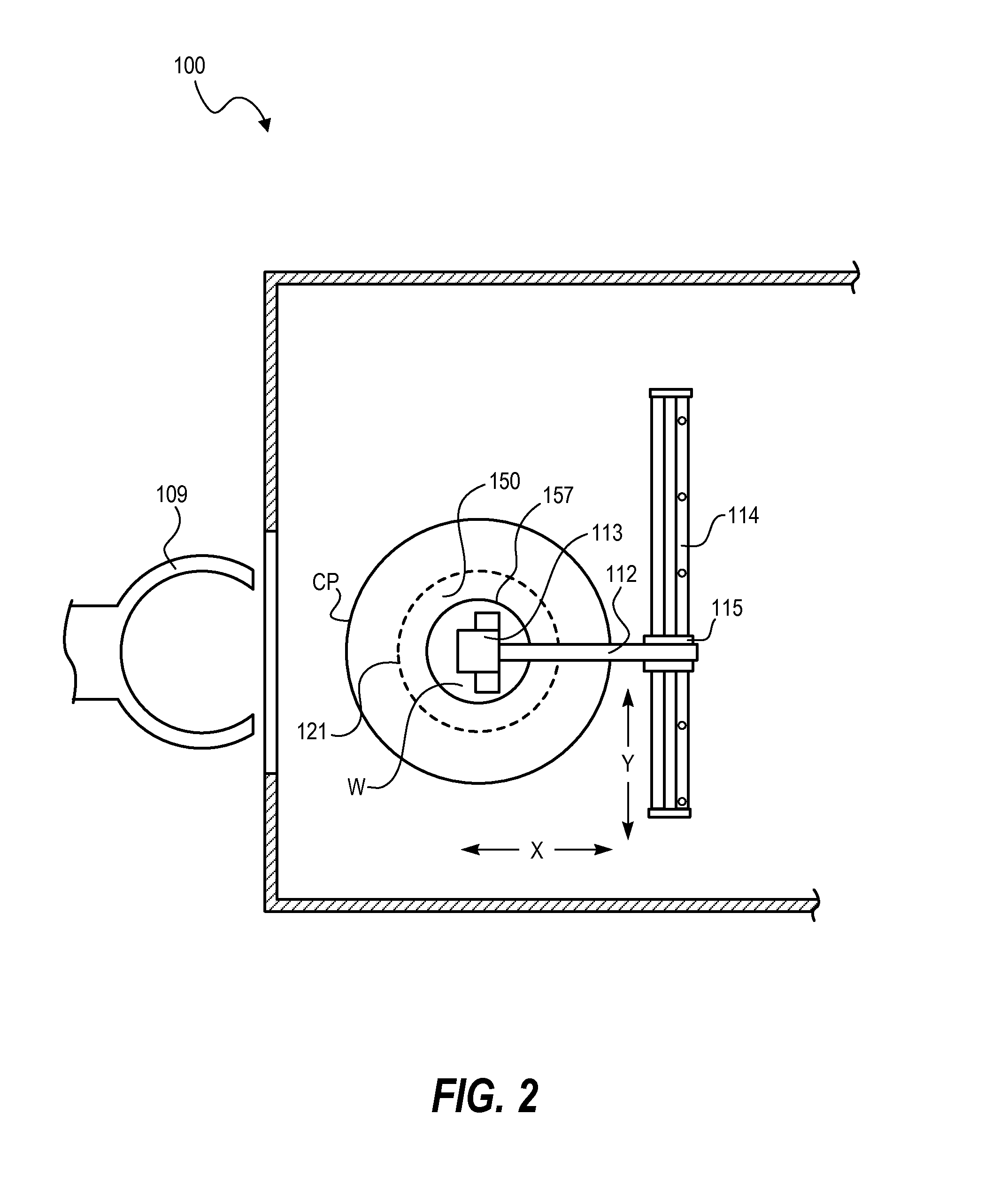
Techniques disclosed herein provide an apparatus and method of spin coating that inhibits the formation of wind marks and other defects from turbulent fluid-flow, thereby enabling higher rotational velocities and decreased drying times, while maintaining film uniformity. Techniques disclosed herein include a fluid-flow member, such as a ring or cover, positioned or suspended above the surface of a wafer or other substrate. The fluid-flow member has a radial curvature that prevents wind marks during rotation of a wafer during a coating and spin drying process.

Description

FIELD OF INVENTION[0001]Techniques disclosed herein relate to spin coating systems and processes, including spin coating of semiconductor substrates.BACKGROUND OF THE INVENTION[0002]Spin coating has been used for decades as method to coat a flat surface with a thin layer of polymer, photo resist, or other compound. Spin coating is typically carried out by depositing a solvent solution, polymer solution, or other liquid material onto a flat substrate. The substrate is then rotated at an angular velocity sufficient to create a centrifugal force that causes the solution to flow outward toward the edge of the substrate, thereby coating the entire surface of the substrate. Excess solution is ejected from the edge of the substrate, and the remaining solution thins and hardens as the solvent evaporates, leaving a thin polymer film.[0003]Such spin coating is a routine step in photolithography used in semiconductor device manufacturing. In an example photolithographic process, a resist spin ...

Claims


Application Information

Patent Timeline
Patent Type & Authority Applications(United States)
IPC IPC(8): H01L21/02H01L21/67
CPCH01L21/6715H01L21/02282B05C11/08G03F7/162H01L21/67034
Inventor BASSETT, DEREK W.PRINTZ, WALLACE P.HOOGE, JOSHUA S.ICHINO, KATSUNORITERASHITA, YUICHIYOSHIHARA, KOUSUKE
Owner TOKYO ELECTRON LTD
Why Eureka
Try Eureka