DC high-voltage super-radiant free-electron based EUV source

a super-radiant free-electron and euv source technology, applied in the direction of cathode ray/electron beam tube circuit arrangement, cathode ray tube/electron beam tube, etc., can solve the problems of high peak power of both higher-harmonic generation and thermally produced plasma processes, and the difficulty in implementing euv generation. , the effect of poor reflection surfa

Inactive Publication Date: 2014-08-28
KLA TENCOR TECH CORP
View PDF7 Cites 10 Cited by
  • Summary
  • Abstract
  • Description
  • Claims
  • Application Information

AI Technical Summary

Benefits of technology

[0020]In some implementations of the method the bunched beam may be compressed laterally to correct electron dispersion or to focus the beam. In some implementations the wavelength of the coherent output radiation may be adjusted by adjusting the electrostatic potential difference between adjacent emitters in the array. In some implementations, a pulse period of the coherent output radiation may be adjusted by selectively switching one or more of the electron emitters on or off so as to adjust a number of beamlets emitted.

Problems solved by technology

However, both higher-harmonic generation as well as thermally produced plasma processes require very high peak power.
While these have proven effective for wavelengths ranging from the far IR to the UV, it becomes difficult to implement FEL for EUV generation because the reflectivity of metals and other mirror coatings drops significantly at shorter wavelengths and thus lack of good reflecting surfaces to form the mirrors.
However, SASE requires a very bright electron beam (i.e., high peak current, low emittance and small energy spread) and a comparatively long undulator to build up beam intensity from spontaneous noise to a saturated intensity.
Because the beam entering the undulator is already bunched, the bulk of the electrons suffer an energy loss from radiating.

Method used


Image

  • DC high-voltage super-radiant free-electron based EUV source
  • DC high-voltage super-radiant free-electron based EUV source
  • DC high-voltage super-radiant free-electron based EUV source

Examples


Embodiment Construction

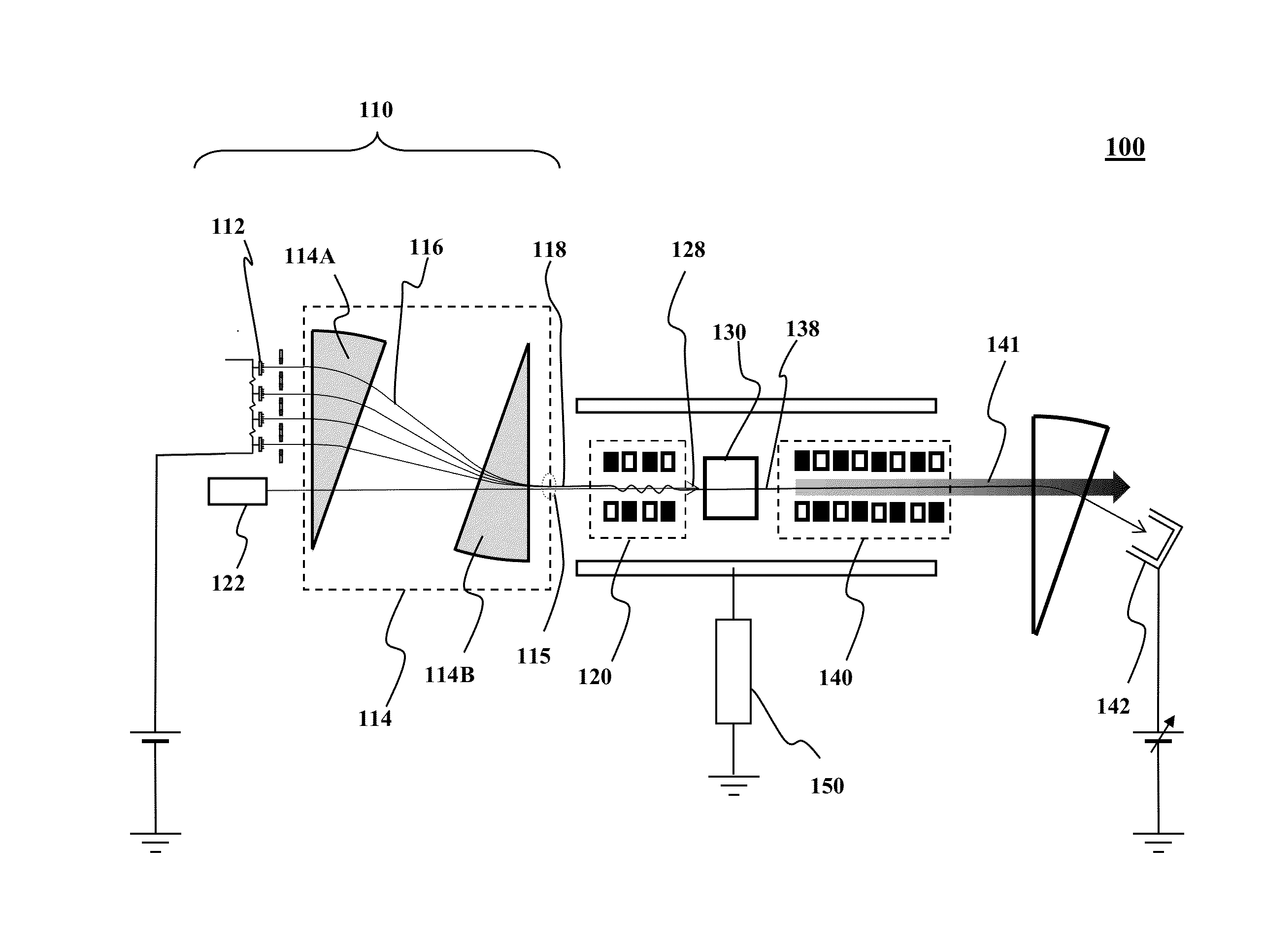
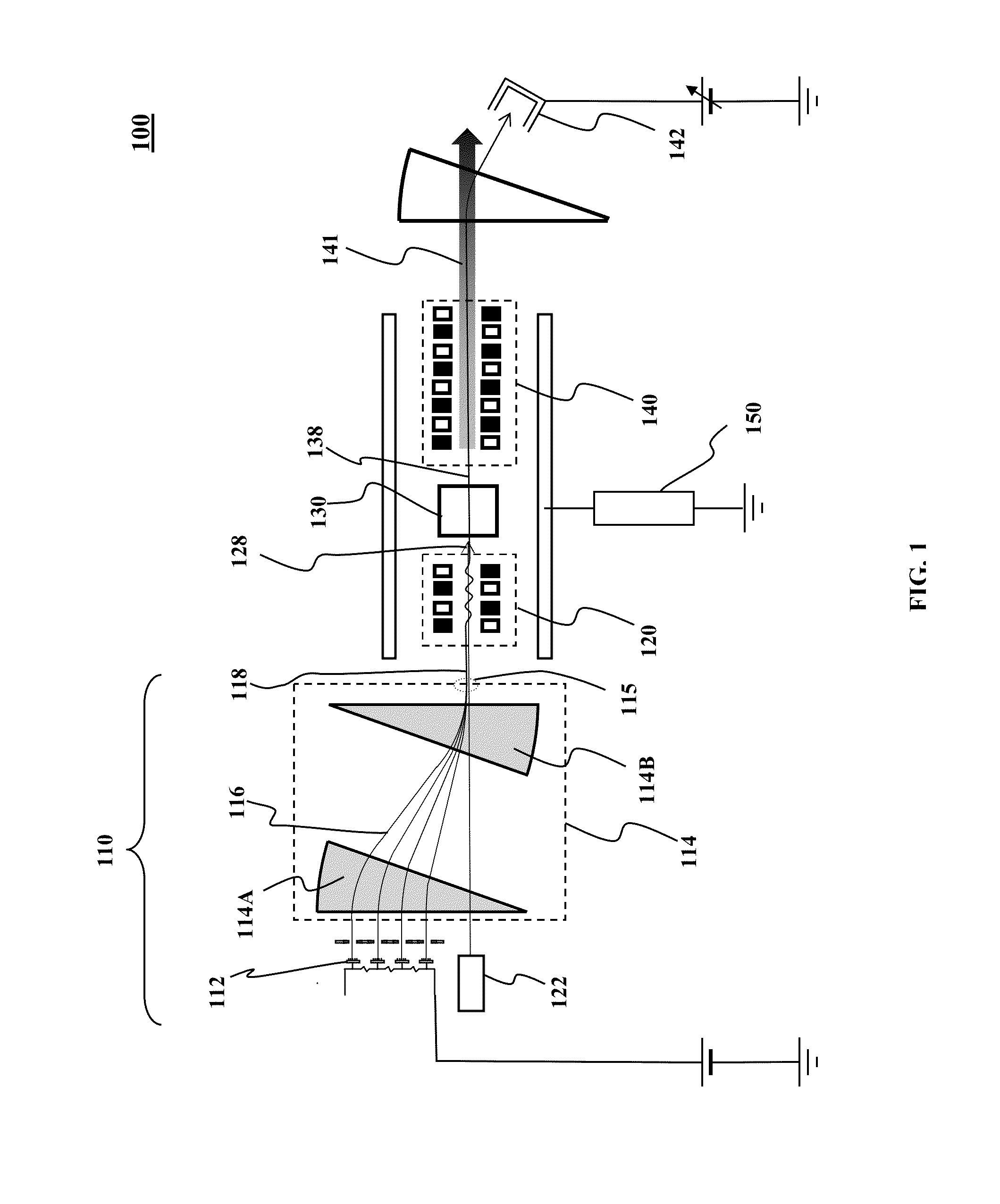
[0026]In the following Detailed Description, reference is made to the accompanying drawings, which form a part hereof, and in which is shown by way of illustration specific embodiments in which the invention may be practiced. The drawings show illustrations in accordance with examples of embodiments, which are also referred to herein as “examples”. The drawings are described in enough detail to enable those skilled in the art to practice the present subject matter. The embodiments can be combined, other embodiments can be utilized, or structural, logical, and electrical changes can be made without departing from the scope of what is claimed. In this regard, directional terminology, such as “top,”“bottom,”“front,”“back,”“leading,”“trailing,” etc., is used with reference to the orientation of the figure(s) being described. Because components of embodiments of the present invention can be positioned in a number of different orientations, the directional terminology is used for purposes...


PUM


Abstract

An array of spatially separated beamlets is produced by a corresponding array of charged particle emitters. Each emitter is at an electrostatic potential difference with respect to an immediately adjacent emitter in the array. The beamlets are converged laterally to form an charged particle beam. The beam is modulated longitudinally with infrared radiation to form a modulated beam. The charged particles in the modulated beam are bunched longitudinally to form a bunched beam. The bunched beam may be modulated with an undulator to generate a coherent radiation output. This abstract is provided to comply with rules requiring an abstract that will allow a searcher or other reader to quickly ascertain the subject matter of the technical disclosure. It is submitted with the understanding that it will not be used to interpret or limit the scope or meaning of the claims.

Description

FIELD OF THE INVENTION[0001]Embodiments of the present invention relate to EUV radiation generation, and more particularly, to an apparatus and a method for generating a EUV radiation source.BACKGROUND OF THE INVENTION[0002]Semiconductor integrated circuits are typically manufactured using a lithographic process. Lithography may involve, e.g., coating a semiconductor wafer with a photosensitive resist, projecting light through a patterned mask onto the resist, and developing the exposed resist. The wavelength of light used in the lithography process is a key factor in the drive for higher levels of microcircuit integration. Since the minimum processing dimension of lithography depends on the wavelength of light used, it is necessary to shorten the wavelength of the irradiated light in order to improve the integration degree of the integrated circuit. In recent years, extreme ultraviolet (EUV) radiation which radiates extreme ultraviolet radiation with wavelengths from 13 nm to 14 nm...

Claims


Application Information

Patent Timeline
Patent Type & Authority Applications(United States)
IPC IPC(8): G21K5/04
CPCG21K5/04H05G2/00H01S3/0903H05H5/04H05H7/04H05H2007/045
Inventor PLETTNER, TOMAS
Owner KLA TENCOR TECH CORP
Why Eureka
Try Eureka