Vertical-coupling transformer with an air-gap structure

a transformer and vertical coupling technology, applied in the field of transformers, can solve the problems of high isolation requirement, preventing the integration of rf off-chip duplexers with cmos technology, large module sizes, and higher costs, and achieves the effects of reducing parasitic capacitance coupling, and improving ant-rx signal coupling

Inactive Publication Date: 2014-08-28
QUALCOMM INC
View PDF9 Cites 17 Cited by
  • Summary
  • Abstract
  • Description
  • Claims
  • Application Information

AI Technical Summary

Benefits of technology

[0011]One particular advantage provided by at least one of the disclosed embodiments, as compared to a vertical transformer without an air-gap, is enhanced performance, such as when implemented in a RF duplexer configuration. For example. TX-RX isolation may be improved due to reduced parasitic capacitance coupling between input inductors and output inductors, ANT-RX signal coupling may be improved due to reduction of the gap width between the input inductors and the output inductors, and ANT-RX insertion loss and TX-ANT insertion loss may be reduced because the air-gap may function as a very low-loss or no-loss dielectric material.

Problems solved by technology

Since modern radio-frequency (RF) duplexers use frequency-selective filters for transmit-receive (TX-RX) isolation, the high isolation requirement prevents integration of the RF off-chip duplexers with CMOS technology.
However, SAW and FBAR technologies result in relatively large module sizes and higher costs as compared to other technologies.

Method used


Image

  • Vertical-coupling transformer with an air-gap structure
  • Vertical-coupling transformer with an air-gap structure
  • Vertical-coupling transformer with an air-gap structure

Examples


Embodiment Construction

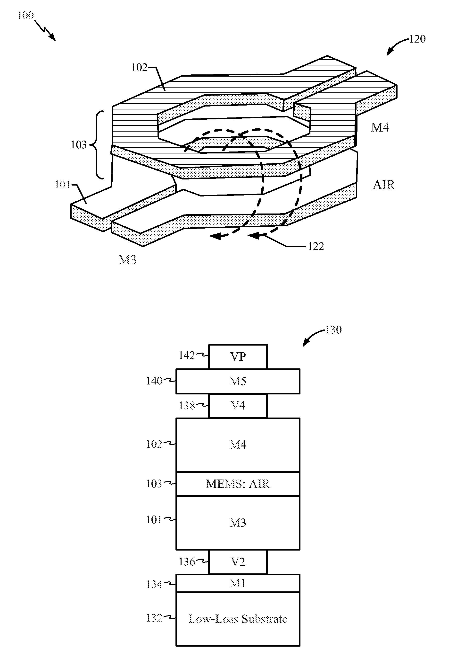
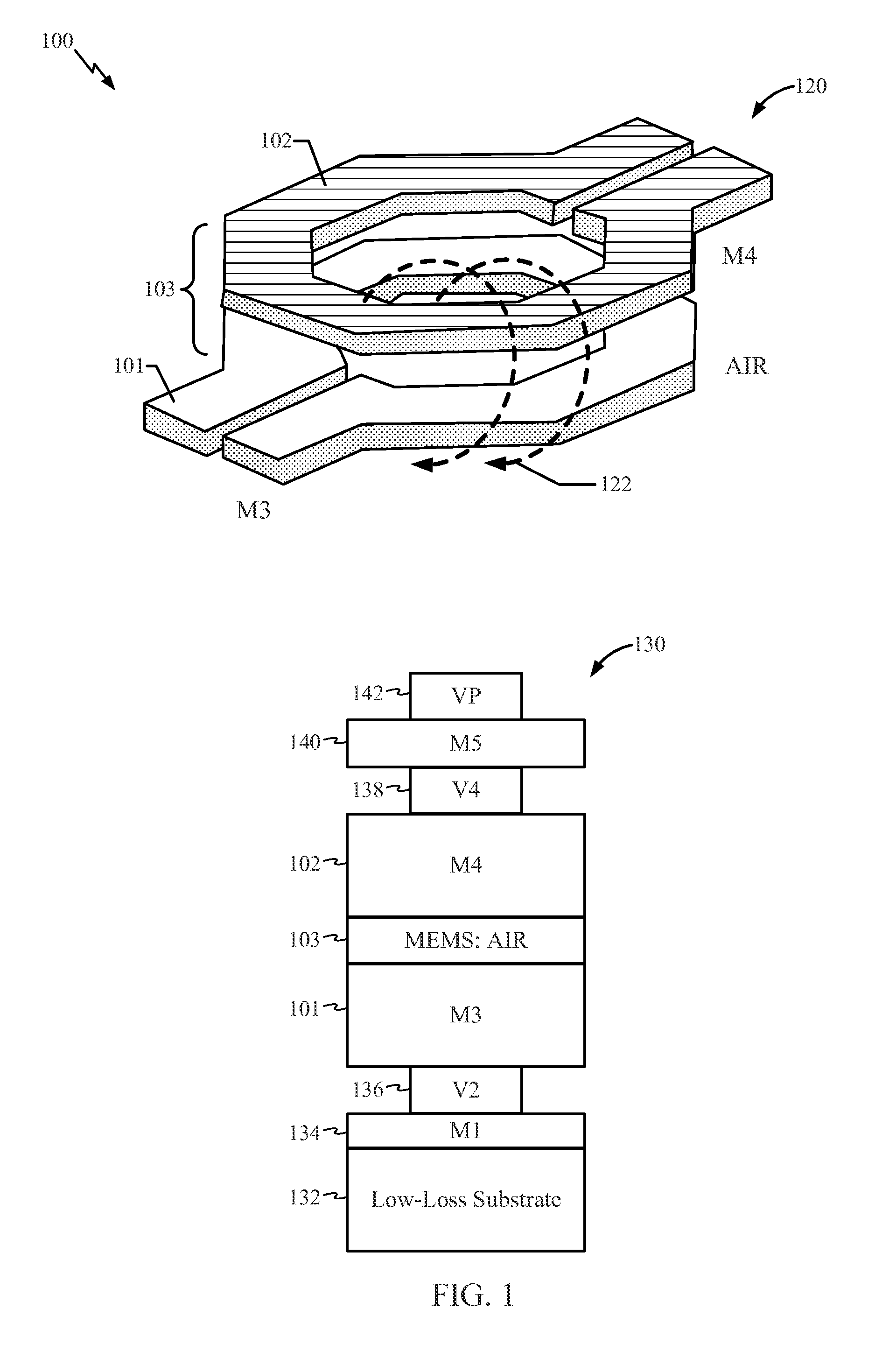
[0032]FIG. 1 is a diagram showing a perspective view of a vertical-coupling transformer (VHT) 120 with an air-gap structure in a passive-on-glass (POG) configuration. The diagram also shows a cross-sectional view 130 of a POG VHT. Particular embodiments of a POG VHT with an air-gap structure and methods of fabrication are presented in details in this disclosure. It should be appreciated, however, that the concepts and insights used in the particular embodiments with respect to designs of the device and with respect to how to make the device may be embodied in a variety of contexts. The particular embodiments presented are merely illustrative of specific ways to design and make the device, and do not limit the scope of this disclosure.

[0033]The present disclosure describes the particular embodiments in specific contexts, such as designs of a VHT with air-gap device and methods of making the device in a POG configuration. However, features, methods, structures or characteristics descr...


PUM

PropertyMeasurementUnit
thicknessaaaaaaaaaa
thicknessaaaaaaaaaa
thicknessaaaaaaaaaa

Abstract

In a particular embodiment, a device includes a low-loss substrate, a first inductor structure, and an air-gap. The first inductor structure is between the low-loss substrate and a second inductor structure. The first inductor structure is aligned with the second inductor structure to form a transformer. The air-gap is between the first inductor structure and the second inductor structure.

Description

I. FIELD[0001]The present disclosure is generally related to transformers in semiconductor devices.II. DESCRIPTION OF RELATED ART[0002]Wireless communication technology has made significant impacts on our society. Numerous technical breakthroughs have helped advance wireless communications. One of the technical breakthroughs is in semiconductor manufacturing processes that enable integration of a large number of microelectronic devices on a semiconductor integrated circuit (IC). Such semiconductor manufacturing technology has helped reduce costs associated with manufacturing wireless communication products.[0003]Complementary-Metal-Oxide-Semiconductor (CMOS) manufacturing technology is typically used in manufacturing wireless communication ICs. Since modern radio-frequency (RF) duplexers use frequency-selective filters for transmit-receive (TX-RX) isolation, the high isolation requirement prevents integration of the RF off-chip duplexers with CMOS technology. Currently, Surface Acou...

Claims


Application Information

Patent Timeline
Patent Type & Authority Applications(United States)
IPC IPC(8): H01F19/00H01F41/04H01F5/00
CPCH01F19/00H01F41/041H01F5/003H01F27/2804H01L28/10H01F2027/2809H01L23/5227H01L2924/0002H05K1/144H05K3/3436H05K2201/041H05K2201/0723Y10T29/4902H01L2924/00
Inventor LAN, JE-HSIUNGLO, CHI SHUNKIM, JONGHAEHONG, JOHN H.
Owner QUALCOMM INC
Why Eureka
Try Eureka