In-situ Compressed Specimen for Evaluating Mechanical Property of Copper Interconnection Micro Column and Preparation Method thereof

a micro-column and specimen technology, applied in the field of compressed specimens for testing mechanical properties of copper interconnection micro-columns, can solve the problems of hard copy, inability to accurately test mechanical properties, and in-situ tensile specimen preparation technology, and achieve the effect of convenient specimen accurate testing

Inactive Publication Date: 2014-08-28
SHANGHAI JIAO TONG UNIV
View PDF2 Cites 6 Cited by
  • Summary
  • Abstract
  • Description
  • Claims
  • Application Information

AI Technical Summary

Benefits of technology

[0011]For shortcomings of the above conventional technique, a purpose of the invention is to provide a copper interconnection micro column mechanical property in-situ compressed specimen and a preparation method thereof, the specimen which only needs a fixed end is easy to achieve the technology, and only one end is fixed in a test, therefore it is easier to accurately test mechanical property of the specimen.

Problems solved by technology

In-situ tensile specimen preparing technology and test method are relatively difficult, for example, the patent for invention with application number of 201210050952.5, the patent application claims an in-situ tensile specimen for TSV copper interconnection material mechanical property test, however the in-situ tensile specimen needs an upper fixed end part and a lower fixed end part, and they are partly in vertical direction with the in-situ tensile specimen, therefore they are hard to be copied.
However, the patent specimen is prepared by adopting common technique, it is not easy to form the circular metal column in the through silicon vias, the process of etching silicon may cause damage to micro column so as to cause accuracy problem of mechanical property test.

Method used


Image

  • In-situ Compressed Specimen for Evaluating Mechanical Property of Copper Interconnection Micro Column and Preparation Method thereof
  • In-situ Compressed Specimen for Evaluating Mechanical Property of Copper Interconnection Micro Column and Preparation Method thereof
  • In-situ Compressed Specimen for Evaluating Mechanical Property of Copper Interconnection Micro Column and Preparation Method thereof

Examples


embodiment 1

Preferred Embodiment 1

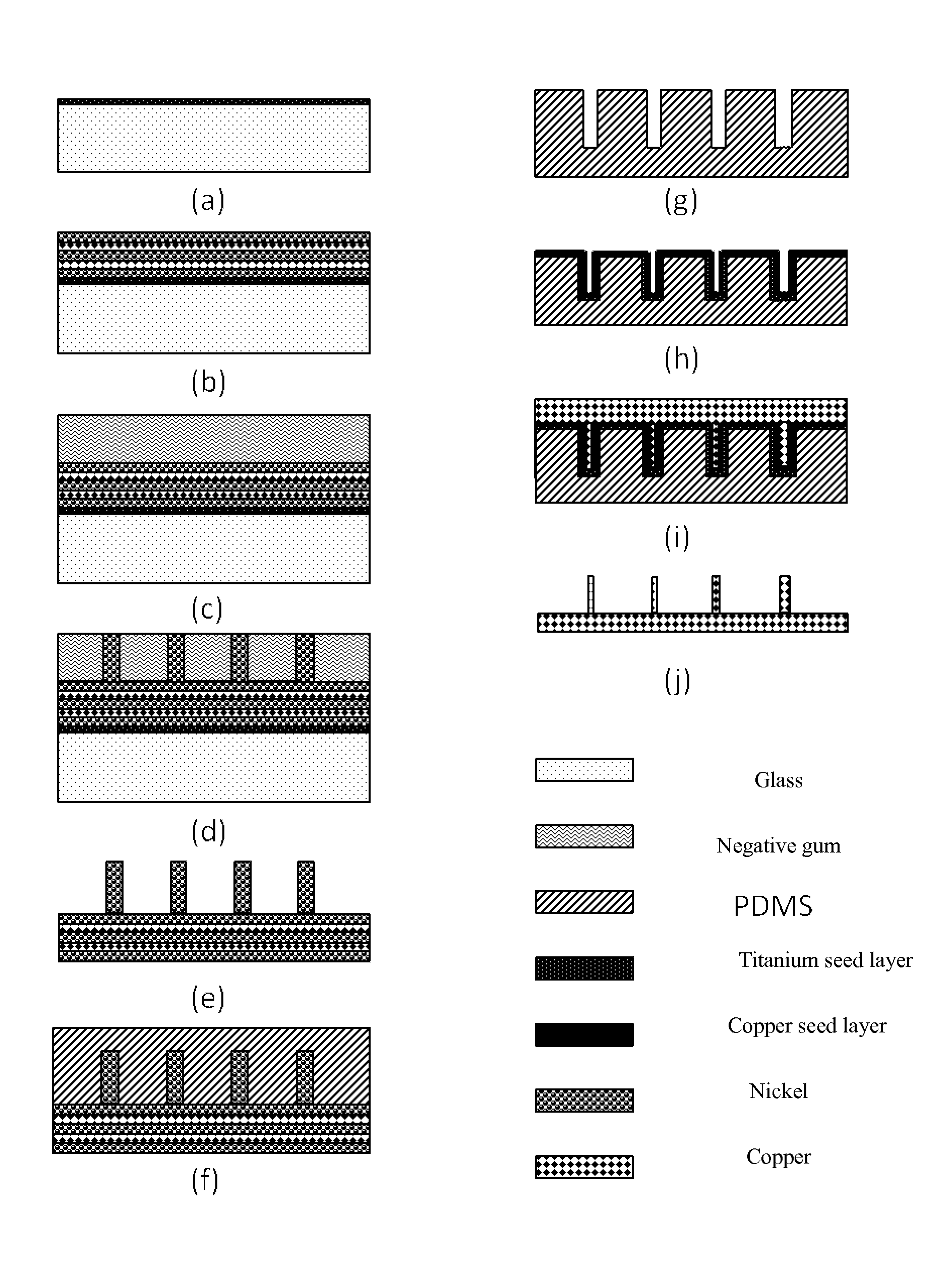
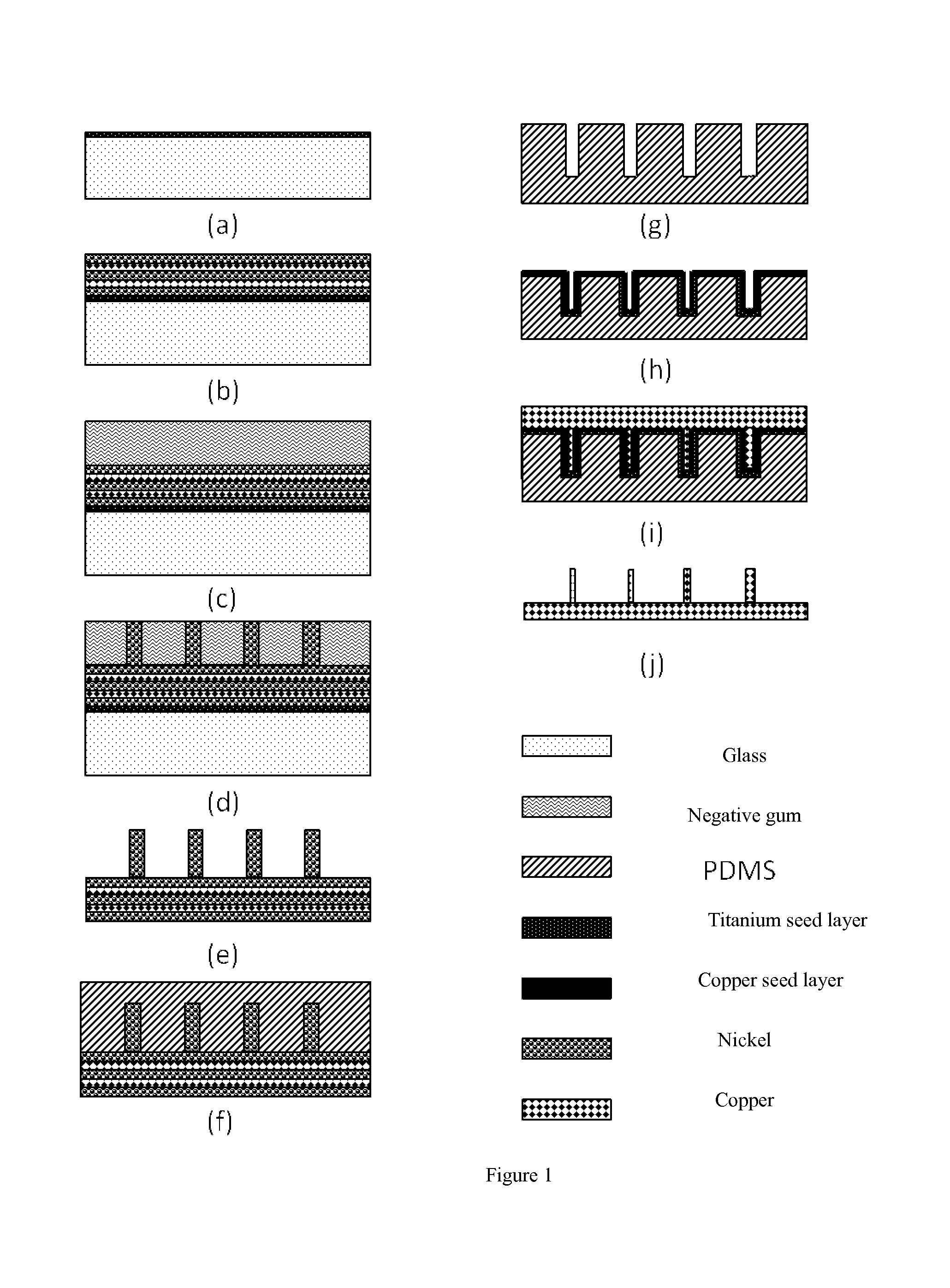
[0040]FIG. 1 shows a specific preparation method. The preparation method comprises steps of: sputtering a titanium seed layer with thickness of about 0.2 μm on a glass sheet; electroplating a copper-nickel layer with total thickness of about 200 μm on the seed layer, wherein the copper-nickel layer is formed by electroplating copper and nickel alternatively and guaranteeing the last layer is nickel layer; spin coating a negative gum layer with thickness of 50 μm on the nickel layer; graphing the negative gum by adopting RIE etching method to form a hole with a diameter of 5 μm and depth of 50 μm; electroplating nickel in the etched hole; removing photo-resist and the seed layer to expose a nickel column adopting copper and nickel as substrate; spin coating a PDMS layer on the nickel column; directly stripping off PDMS from the nickel column after a curing treatment; sputtering a titanium seed layer with thickness of 0.2 μm and a copper seed layer with thickness...

embodiment 2

Preferred Embodiment 2

[0048]FIG. 1 is a detailed preparing method. The method comprises steps of: sputtering a titanium seed layer with thickness of about 0.4 μm on a glass sheet; electroplating a nickel layer with total thickness of 250 μm on the seed layer; spin coating negative gum with thickness of 150 μm on the nickel layer; graphing the negative gum by using an RIE etching method to form a hole with a diameter of 25 μm and depth of 150 μm; electroplating nickel in the etched hole; removing photo-resist and the seed layer to expose a nickel column which adopts nickel as substrate; spin coating a PDMS layer on the nickel column; directly stripping off PDMS from the nickel column after a curing treatment; sputtering a titanium seed layer with thickness of 0.15 μm and a copper seed layer with thickness of 0.6 μm on the PDMS which has been stripped off; electroplating copper to form a copper interconnection micro-column structure with a high aspect ratio; finally stripping off the ...

embodiment 3

Preferred Embodiment 3

[0056]FIG. 1 shows a detailed preparing method. The method comprises steps of: sputtering a titanium seed layer with thickness of about 0.5 μm on a glass sheet; electroplating a copper-nickel layer with total thickness of 250 μm on the seed layer, wherein the copper-nickel layer is formed by electroplating copper and nickel alternatively and guaranteeing the last layer is nickel layer; spin coating a negative gum layer with thickness of 200 μm on the nickel layer; graphing negative gun by adopting RIE etching method to form a hole with a diameter of 5 μm and depth of 50 μm; electroplating nickel in the etched hole; removing photo-resist and the seed layer to expose the nickel column adopting copper and nickel as substrate; spin coating a PDMS layer on the nickel column; directly stripping off PDMS from the nickel column after a curing treatment; sputtering a titanium seed layer with thickness of 0.25 μm and a copper seed layer with thickness of 0.8 μm on the st...


PUM

PropertyMeasurementUnit
thicknessaaaaaaaaaa
thicknessaaaaaaaaaa
depthaaaaaaaaaa

Abstract

An in-situ compressed specimen of copper interconnection micro column, which is a circular metal column formed in a PDMS hole, includes: a specimen part and a fixed end part for fixing the specimen; wherein the fixed end part is a circular or square plate structure, the specimen part is an upper part of the fixed end part; a main body of the present invention is of micron order, a forced direction of the specimen is consistent with a growth direction of the metal column. A method of electroplating copper column by adopting PDMS as template substrate is applied to overcome a problem that TSV is corrosive to the copper column during a silicon etching process so as to affect a mechanical property accuracy test, the method is advanced in shortening test process period, achieving good reproducibility and high yield.

Description

CROSS REFERENCE OF RELATED APPLICATION[0001]This is a U.S. National Stage under 35 U.S.C 371 of the International Application PCT / CN2013 / 073133, filed Mar. 25, 2013, which claims priority under 35 U.S.C. 119(a-d) to CN 201310039874.3, filed Feb. 1, 2013.BACKGROUND OF THE PRESENT INVENTION[0002]1. Field of Invention[0003]The invention relates to a compressed specimen for testing mechanical property of copper interconnection micro column and a preparation method thereof, specifically to an in-situ compressed specimen for simulating TSV copper interconnection material mechanical property test and a preparation method thereof.[0004]2. Description of Related Arts[0005]TSV (Through Silicon Vias) lamination interconnection technique can improve three-dimensional integration level and reduce interconnection delay with advantage of shortening the distance, it is an important direction for microelectronic technology development. As the preparation technology and structure size of copper inter...

Claims


Application Information

Patent Timeline
Patent Type & Authority Applications(United States)
IPC IPC(8): B81C1/00
CPCB81C1/00015B81C1/00111B81C2201/032G01N3/08G01N2203/0298Y10T428/12389
Inventor WANG, HONGWANG, ZHAOYUCHENG, PINGDING, GUIFUGU, TINGWANG, HUIYINGZHANG, CONGCHUN
Owner SHANGHAI JIAO TONG UNIV
Why Eureka
Try Eureka