The
balloon style of construction has mostly been discontinued due to a number of factors, including, but not limited to the overall low
fire resistance and the high cost of lengthy studs, which together inhibits the use of the
balloon method of construction in multi-story buildings.
Blocking
noise from floor-to-floor is the most common, yet challenging request in
soundproofing.
However, flooring products really have a substantial effect only on
impact sounds.
1. Use of actual flooring materials as soundproof material. Obviously, and as said in the aforementioned article, different flooring materials have very different sound transfer qualities. Carpet flooring, for an example, is a material with one of the highest soundproof ratings. However, it is highly problematic due to a number of factors, including, but not limited to, the major known issues of
indoor air quality, and serviceability issues associated with particle residue retained between the carpet pad and carpet itself. Such residue is known to cause allergies,
breathing problems, respiratory infections and
asthma. Furthermore, accumulation of
moisture and, as a consequence, most likely growing
bacteria such as mold that is not removable by means of regular cleaning, creates a major problem for the consumers, not to mention the overall high maintenance factor.
2. Use of sound control underlayment, such as
cork or even an engineered
noise control insulation mat that is intended to limit only a certain percentage of
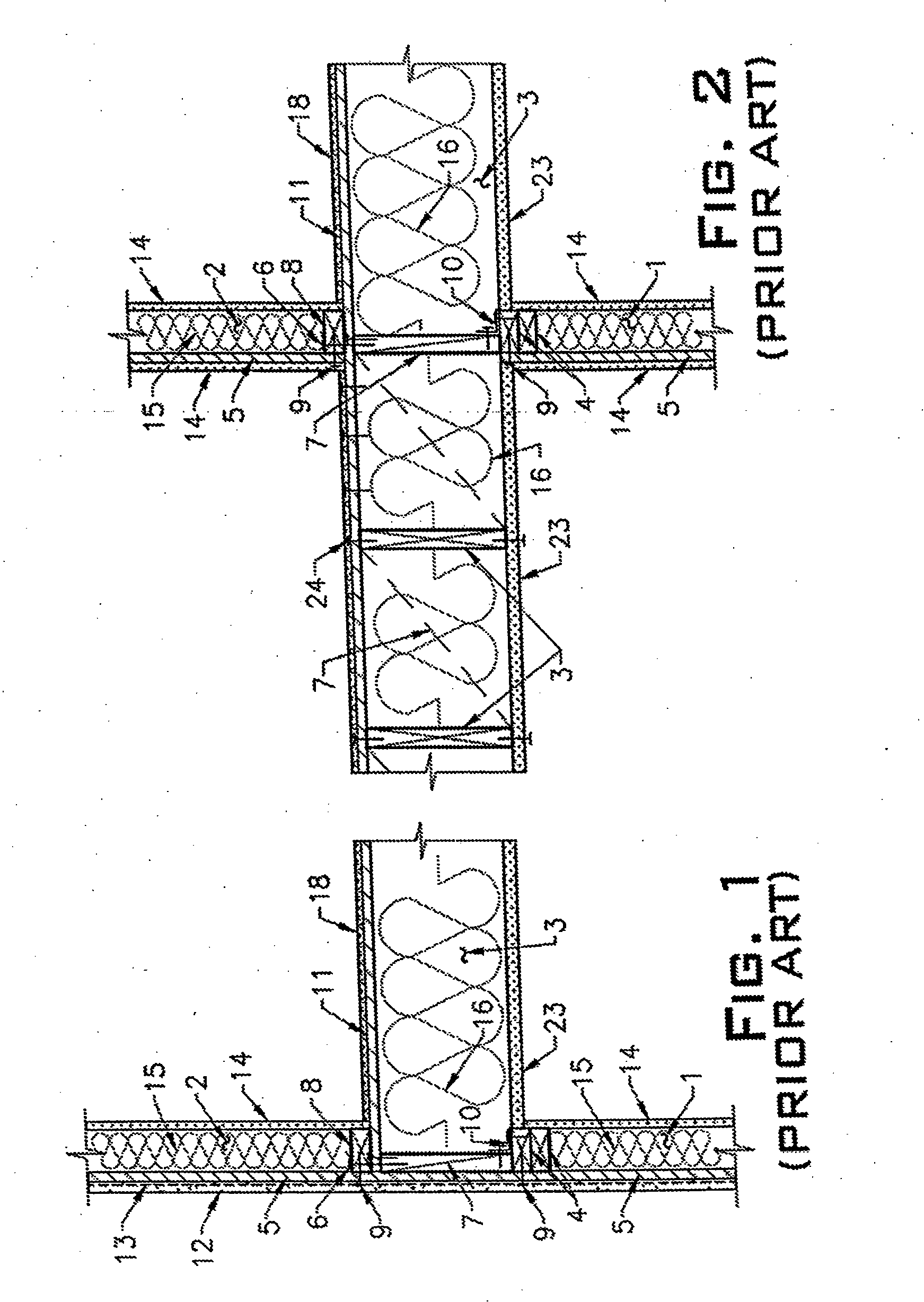
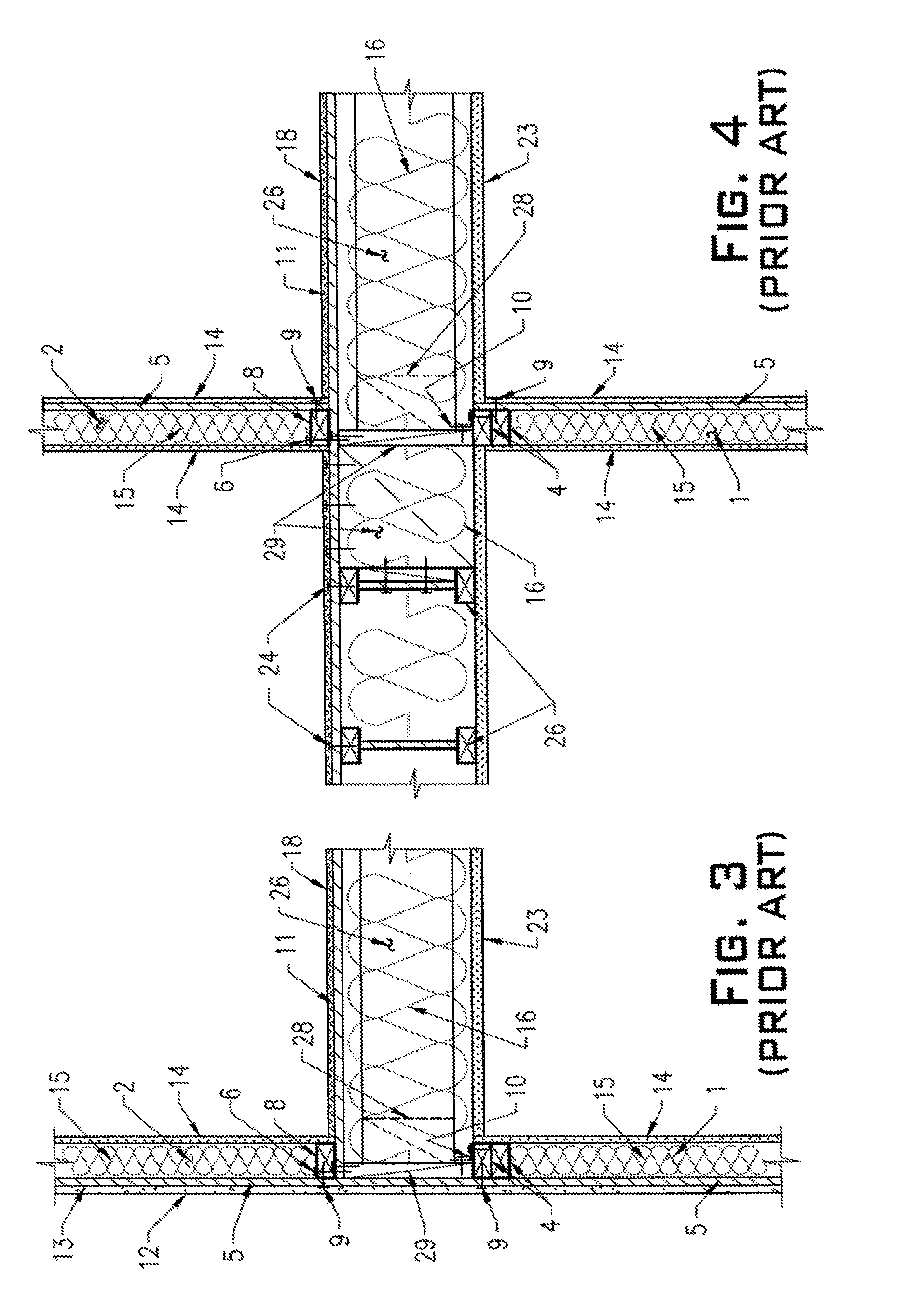
impact noise between the floors. If sound control underlayment is employed, it is normally installed between the flooring 18 and plywood sheathing 11 (refer to FIGS. 1 to 4). Sound control underlayment is not called out in FIGS. 1 to 4 since it does not embody the
industry standard or mandatory requirement in all the typical cases.
3. Interior
drywall sheathing 23 per FIGS. 1 to 4 or, in older construction, use of so called acoustic ceiling, also known in the industry as “popcorn ceiling” instead of
drywall sheathing 23. The “popcorn ceiling” can be found in some of the older structures since it was popular from the late 1950's through the early 1980's. Even if difficulty in cleaning and the issue of architectural appearance are negated and not considered as main factors against use of acoustic ceilings, the main prohibiting factor against this type of ceiling today is the presence of
asbestos.
Interior
drywall sheathing 23 itself is not very effective as a primary sound reduction
system.
Obviously, such an approach offers a less than desirable solution from both the design gravity load standpoint and the design lateral load increase standpoint.
Although the acoustic
engineering society has made attempts in the past to work on finding a solution in form of an improvement in the current state of the art, the building
community has created an opposition that has thus far blocked these attempts due to the increase in the cost of construction.
However, a lack of a proper noise blocking barrier can lead to medical problems associated with
exposure to noise.
Complications, related to the
exposure to certain levels of noise in different environments, may result in an undesirable outcome.
Currently, the industry has not yet offered to the
consumer a floor-to-floor noise blocking barrier that can operate in the high 80s
decibel range or even 90
decibel range, despite the tendency toward higher
population densities in urban areas.
This situation automatically leads to development of higher stresses within the horizontal diaphragm.
This offers an almost cost prohibitive, less than practical solution that also increases the dead load of the structure, inadvertently causing an increase in the design seismic load.
The natural difference in stiffness between the typical 2×
joist and a 4× or 3× wood beam used as a
joist in case of uniform long floor diaphragm may also invite issues with uneven gravity
load distribution and transfer within the floor
system, posting unexpected potential issues with overall floor
system long term performance.
Obviously, use of 4× or 3× wood beams do not offer an acceptable solution for the issues (1), (2) and (3) above.
Not utilizing flooring as part of the
structural system of the building traditionally creates challenges in the industry, including, but not limited to, moot points during the
design phase.
Often times, not being able to define and, therefore, not knowing the weight of the flooring material while the architectural design decisions related to the flooring choice has not been made or is being changed numerous times during the
design process inserts a definiteness issue between the offices of the architect and the engineer.
This negatively affects both cost of the design and cost of the project during the construction phase.
Conservative design for an additional weight may not always represent the safest and most economical design.
Although the aforementioned document also states that “Diaphragm failures are less commonly observed in earthquakes,” the same document reveals a significant problem related to “the disruption caused by strengthening the diaphragm [that] can be quite significant, so diaphragm
rehabilitation is less commonly employed than adding global strength and stiffness, or improving connection paths.”
Although FEMA 547 addresses the existing wood structural panel diaphragm related issues, mentioning that “an issue that often arises is whether existing joists, which are typically thicker than the code assumed 1½″, can count as 3× blocking.
Another problem related to the use of the proposed remedies by FEMA such as the wood structural panel sheathing
overlay technique(s) is the imposition of permanent weight (dead load) onto the existing
structural system that may be incapable of carrying such additional dead load without strengthening and / or structural alterations.
Without analysis of the existing structure and possible strengthening of the gravity load resisting system of the existing structure, such an increase in dead load creates an additional burden in form of the overstress, excessive deflections, or in some rare cases even a so called near failure state situation within the existing gravity load resisting system that exists in the older buildings.

