

Electrochemical cell used in production of hydrogen using cu-cl thermochemical cycle
- Summary
- Abstract
- Description
- Claims
- Application Information
AI Technical Summary
Benefits of technology
Problems solved by technology
Method used
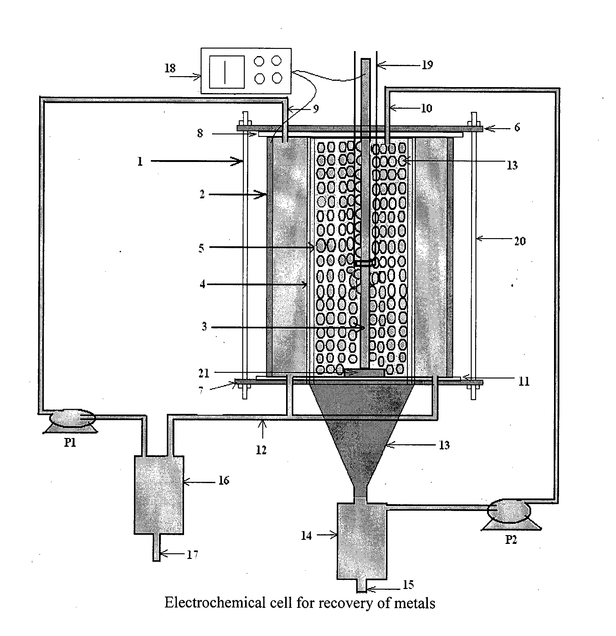
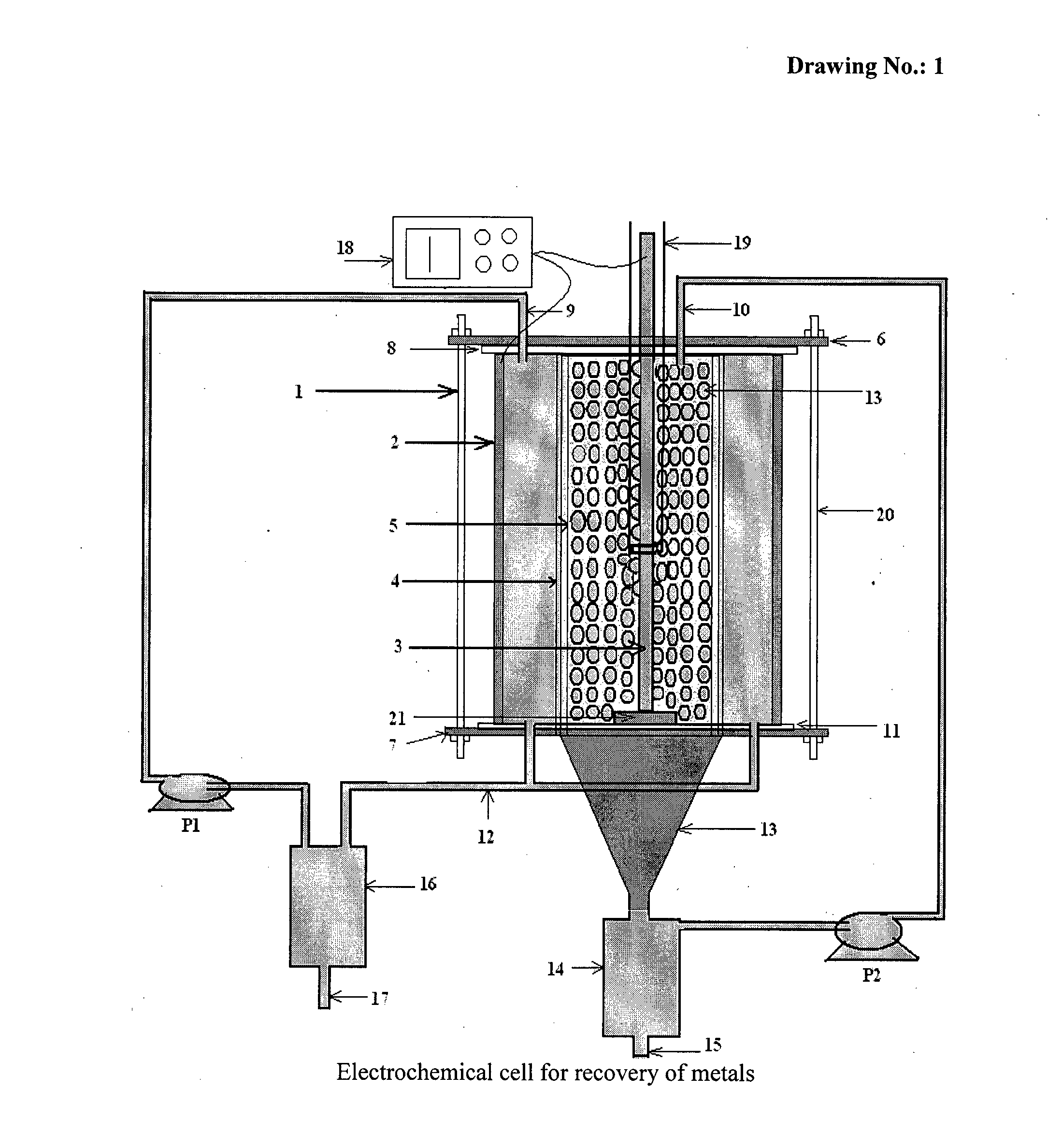
Image

Examples
example 1
[0056]According to the present invention, the experiments of recovery of copper metal by electrolysis of cuprous chloride were carried out in the above mentioned electrochemical cell using cuprous chloride in hydrochloric acid as electrolyte. The electrolyte was pumped through their respective compartments using peristaltic pump.
[0057]Recovery of copper metal from cuprous chloride was carried out at room temperature by applying 100 mA / cm2 cathodic current density. The scaning electron microscopy (SEM) image obtained for copper metal formed during electrolysis is shown in FIG. 5. The X-Ray Diffraction (XRD) pattern of deposited copper is shown in FIG. 6.
example 2
[0058]According to the present invention, the experiments of recovery of silver metal by electrolysis of silver nitrate were carried out in the above mentioned electrochemical cell using silver nitrate in nitric acid as electrolyte. The electrolyte was pumped through their respective compartments using peristaltic pump.
[0059]Recovery of silver metal from silver nitrate was carried out at room temperature by applying 60 mA / cm2 cathodic current density. The scaning electron microscopy (SEM) image obtained for silver metal formed during electrolysis is shown in FIG. 7. The X-Ray Diffraction (XRD) pattern of deposited silver is shown in FIG. 8.
example 3
[0060]According to the present invention, the experiments of recovery of zinc metal by electrolysis of zinc nitrate were carried out in the above mentioned electrochemical cell using zinc nitrate in nitric acid as electrolyte. The electrolyte was pumped through their respective compartments using peristaltic pump.
[0061]Recovery of zinc metal from zinc nitrate was carried out at room temperature by applying 100 mA / cm2 cathodic current density. The scaning electron microscopy (SEM) image obtained for zinc metal formed during electrolysis is shown in FIG. 9. The X-Ray Diffraction (XRD) pattern of deposited zinc is shown in FIG. 10.
PUM
| Property | Measurement | Unit |
|---|---|---|
| Fraction | aaaaa | aaaaa |
| Fraction | aaaaa | aaaaa |
| Particle size | aaaaa | aaaaa |
Abstract
Description
Claims
Application Information