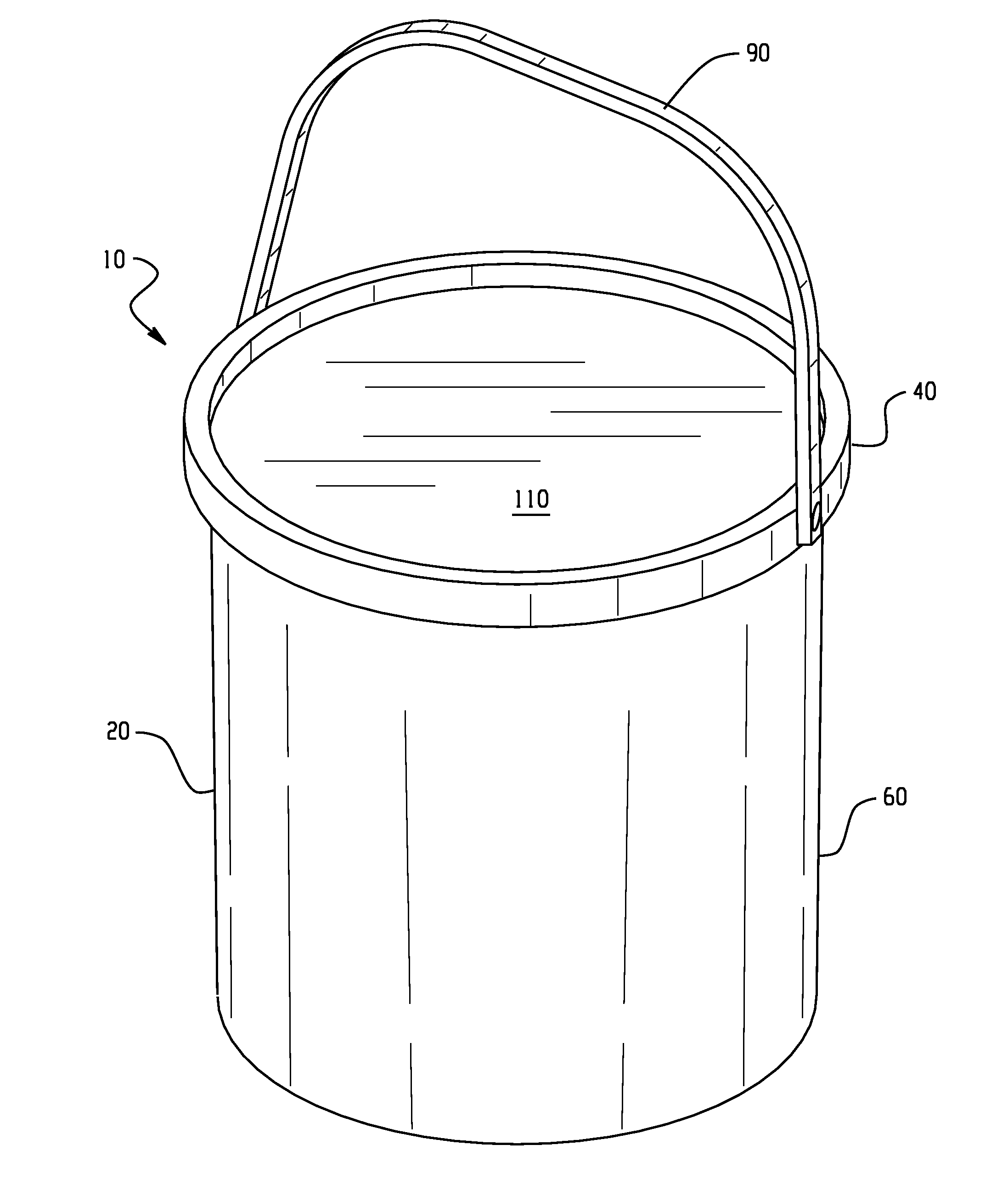
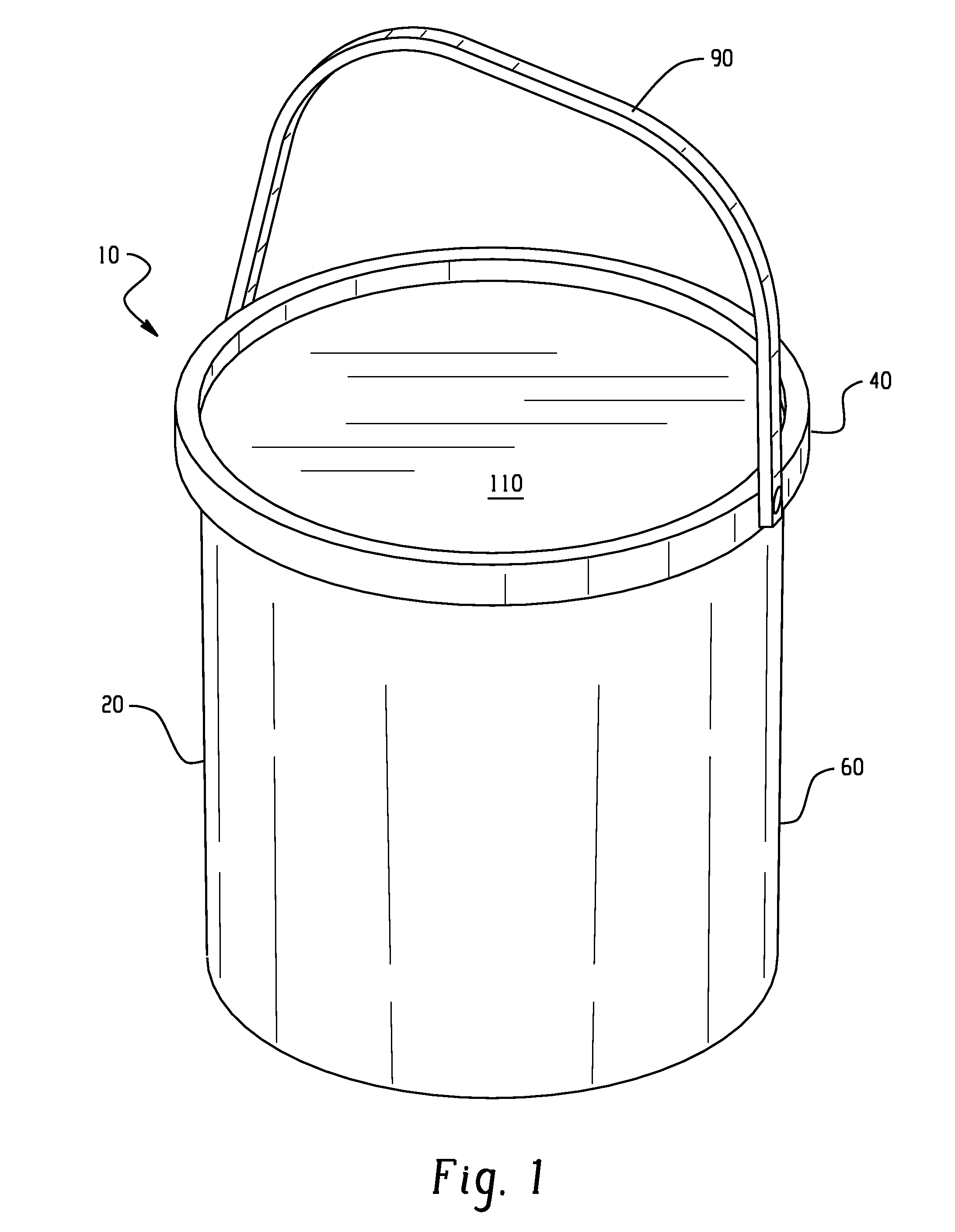
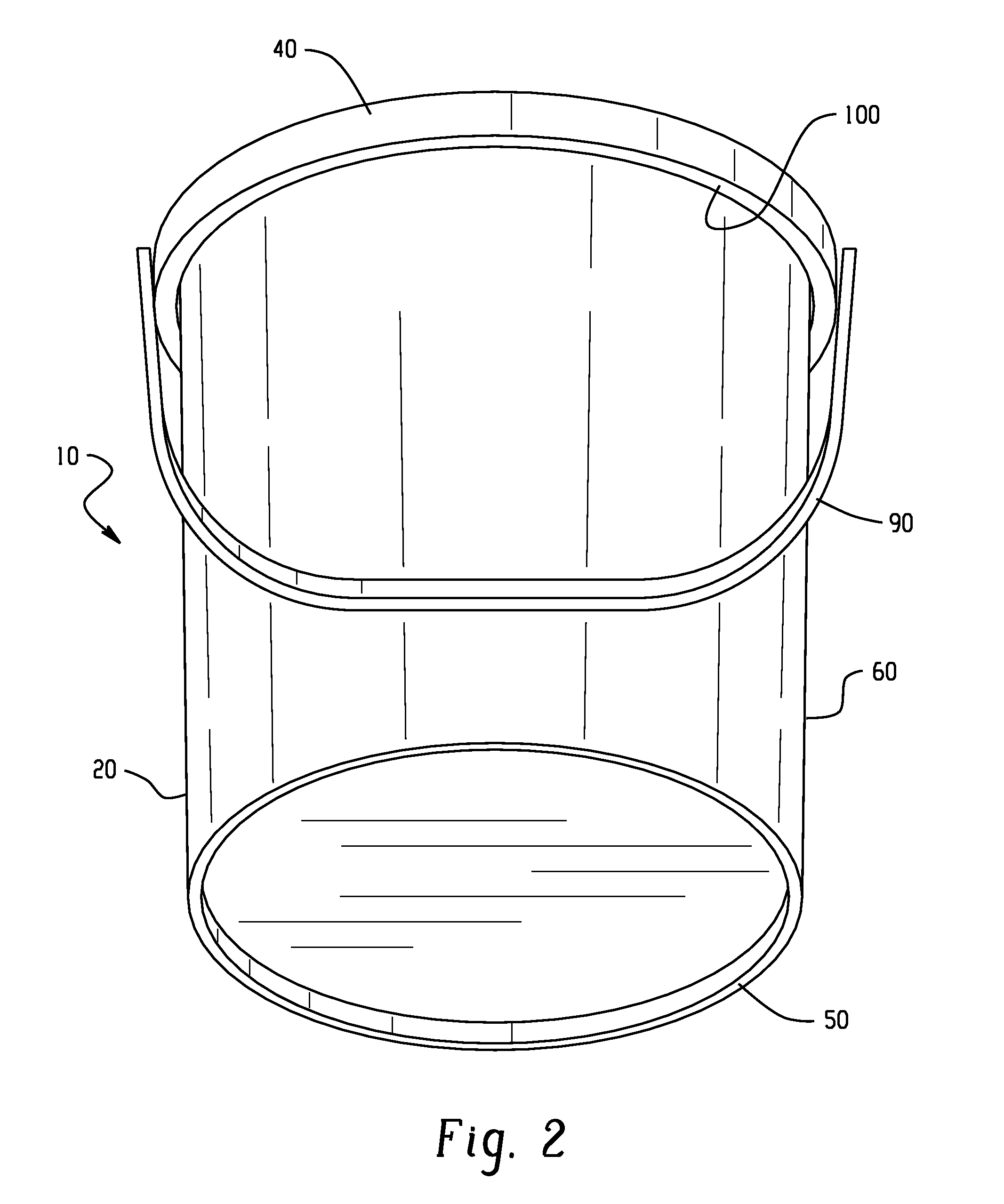
Meltable crack sealant packaging

Active Publication Date: 2014-09-04
P & T PROD
View PDF10 Cites 3 Cited by
  • Summary
  • Abstract
  • Description
  • Claims
  • Application Information

AI Technical Summary

Benefits of technology

[0013]Packaging according to the invention can be melted together with the crack sealant composition contained within using conventional crack sealant heating equipment, and once melted becomes an accessory component of the applied crack sealant composition that imparts desirable properties including, but not limited to, lower surface tack, higher softening point and lower penetration. Packaging according to the invention is very rugged and can be handled during transit and/or on the job site in a rough manner without concern that the packaging will become damaged. The packaging is watertight, and can be stored outside in all weather conditions without damage to the packaging or to the crack seal

Problems solved by technology

The use of crack sealants prolongs the service life of such pavement surfaces.
Disadvantageously, the corrugated boxes must be collected at the job site for recycling.
In blustery conditions, the empty corrugated boxes can be blown away from their intended staging location.
In wet conditions, the corrugated boxes can break down before or after the crack sealant has been used.
And, the corrugated boxes are susceptible to damage (e.g., deformation) due to compression (e.g., from the weight of the material itself, when stacked).
Disadvantageously, containers of this t

Method used


Image

  • Meltable crack sealant packaging
  • Meltable crack sealant packaging
  • Meltable crack sealant packaging

Examples


example 1

[0032]800 grams of an all-climate hot pour crack sealant (Dura-Fill HS available from P&T Products, Inc. of Sandusky, Ohio) was melted and then tested in accordance with ASTM Tests D 5239-09, D 36 and modified D 3121. The modifications to D 3121, which is a Standard Test for Tack of Pressure-Sensitive Adhesives by Rolling Ball, involved pouring the molten crack sealant material at a temperature of 345° F. into a metal tack test mold (3″ wide×10″ long×0.125″ deep) lined with release paper. After the crack sealant material was allowed to cool at room temperature (˜72° F.) for two hours, the track was inclined at an angle of 10°. A 7 / 16″ steel ball was placed atop the test track, the ball released, and allowed to roll down the track onto the solidified material. The distance of travel by the ball was measured and recorded in millimeters. Throughout the instant specification and in the appended claims the term “modified ASTM D 3121” shall refer to the ASTM D 3121 test as modified above....

example 2

[0033]850.8 grams of the same crack sealant used in Example 1 and 1.80 grams of poly bag material were melted together and tested using the same testing procedures as indicated in Example 1. The ratio of crack sealant material and poly bag material was intended to approximate as closely as possible the amount of poly bag material melted into the crack sealant material when the same is packaged using a conventional poly-bag lined cardboard box. The testing results are reported in Table I.

example 3

[0034]804.4 grams of the same crack sealant used in Example 1 and 44 grams of expanded polystyrene were melted together and tested using the same testing procedures as indicated in Example 1. The ratio of crack sealant material and expanded polystyrene was intended to approximate as closely as possible the amount of expanded polystyrene melted into the crack sealant material when the same is packaged as described in U.S. Pat. No. 8,017,681 to Guymon et al. The testing results are reported in Table I.


PUM

PropertyMeasurementUnit
Temperatureaaaaaaaaaa

Abstract

A meltable crack sealant package that includes a polymeric container and a crack sealant material contained therein. The polymeric container includes a bottom portion including a rigid base and an upwardly extending rigid sidewall that terminates in and define an opening. The rigid base and upwardly extending rigid sidewall cooperate to define a reservoir. A rigid lid portion operatively engages with the bottom portion to close off the opening and thereby seal the crack sealant material within the reservoir in a watertight manner. Methods of making and using the meltable crack sealant package are also disclosed.

Description

BACKGROUND OF INVENTION[0001]1. Field of Invention[0002]The present invention relates to crack sealant packaging and methods of packaging crack sealant and using the same.[0003]2. Description of Related Art[0004]“Crack sealant” is general term for materials which are used to fill and thereby seal cracks and joints in asphalt and cement pavement surfaces. Crack sealant materials are sometimes also referred to in the art by terms such as, for example: hot pour; crack seal; crack sealer; crack sealant; crack fill; crack filler; joint seal; joint sealer; joint sealant; joint fill; joint filler; rubberized asphalt; tar; polymer-modified asphalt; thermoplastic-modified asphalt; para-plastic materials; rubber-modified asphalt; traffic loop detector sealant; waterproofing membrane asphalt; modified asphalt; roofing asphalt; cold joint adhesives; marker adhesives; and other asphalt / resin / polymer compositions. Throughout the present specification and in the appended claims, the term “crack se...

Claims


Application Information

Patent Timeline
IPC IPC(8): B65D81/18B29C39/00E01C11/00
CPCB65D81/18B29C39/003E01C11/005B29C39/10B29K2995/0069B65D21/0219B65D25/32B65D43/0212B65D71/0096B65D2543/00092B65D2543/00296B65D2543/00537B65D2543/00629B65D2543/00685B65D2543/0074B65D2543/00796
Inventor FINDLEY, JENNIFERDRANICHAK, DEREK
Owner P & T PROD
Why Eureka
Try Eureka