Partial upgrading process for heavy oil and bitumen

a technology of heavy oil and upgrading process, which is applied in the direction of gas purification with selectively adsorption solids, inorganic chemistry, liquid washing, etc., can solve the problems of easy conversion, undesirable waste material, and fraction must be removed

Active Publication Date: 2014-09-18
EXPANDER ENERGY
View PDF3 Cites 15 Cited by
  • Summary
  • Abstract
  • Description
  • Claims
  • Application Information

AI Technical Summary

Problems solved by technology

Further, refineries are not suited to processing heavy oil, bitumen etc. and thus the viscosity, density and impurity content, such as heavy metals, sulfur and nitrogen, present in such heavy materials must be altered to permit refining.
One of the problems with heavy oil and bitumen upgrading is that the asphaltenes and the heavy fraction must be removed or modified to create value and product yield.
Typical upgraders exacerbate the problem by the formation of petcoke or residuum which results in undesirable waste material.
This material, since it cannot be easily converted by conventional methods, is commonly removed from the process, reducing the overall yield of valuable hydrocarbon material from the upgrading process.
The overall process is quite effective, however, it does not take advantage of the conversion of synthesized streams which are useful for introduction into the hydroprocessing unit for production of synthetic crude, the recycling of unique streams for use in the upgrader, nor is there any teaching specifically of the integration of the Fischer-Tropsch process or the recognition of the benefit to the process of using a SMR and/or ATR in the process circuit to maximize SCO yields and reducing dependence on natural gas.
Similar to the process taught in U.S. Pat. No. 7,407,571, this process has utility, however, it limits the conversion of the otherwise wasteful asphaltene to production of

Method used


Image

  • Partial upgrading process for heavy oil and bitumen
  • Partial upgrading process for heavy oil and bitumen
  • Partial upgrading process for heavy oil and bitumen

Examples


Embodiment Construction

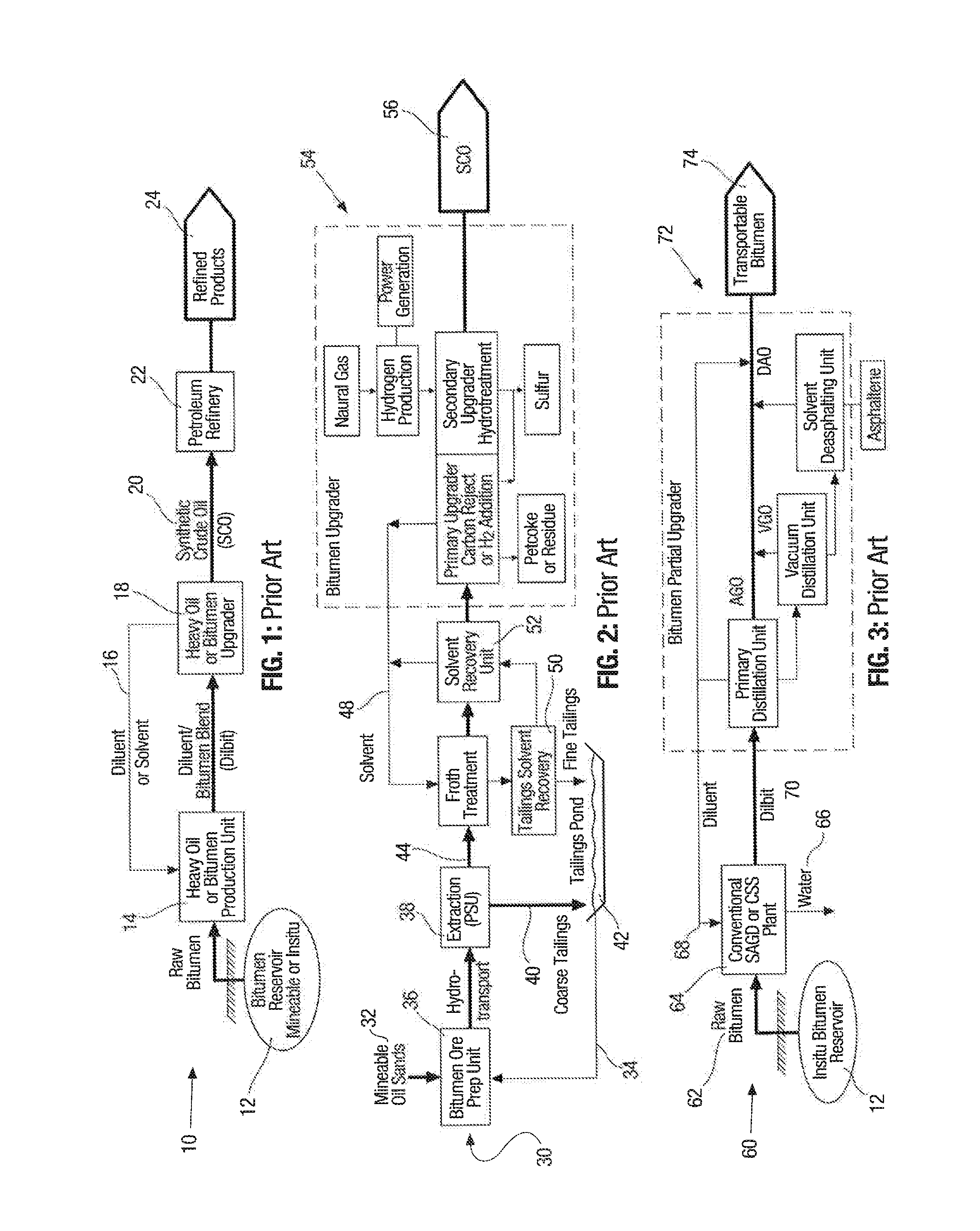
[0096]Referring now to FIG. 1, shown is a first embodiment of a bitumen production flow diagram based on the prior art. The overall process is denoted by 10. In the process, the heavy oil or bitumen source 12 may comprise a bitumen reservoir which may be minable or in situ. Generally speaking, the bitumen then may be transported to a heavy oil or bitumen production unit 14 into which diluent or solvent may be introduced via line 16 from a heavy oil or bitumen upgrader 18. The diluent or solvent can comprise any suitable material well known to those skilled in the art such as suitable liquid alkanes as an example. Once the diluent is introduced via line 16 into the production unit 14, the result is a mobilizable bitumen blend (dilbit). Once the dilbit or diluted bitumen blend is processed in the upgrader 18, the so formed synthetic crude, globally denoted by 20 is then treated in a petroleum refinery 22 where subsequently refined products are formulated and with the refined products ...


PUM

PropertyMeasurementUnit
Fractionaaaaaaaaaa
Percent by volumeaaaaaaaaaa
Boiling pointaaaaaaaaaa

Abstract

A bitumen and heavy oil upgrading process and system is disclosed for the synthesis of hydrocarbons, an example of which is synthetic crude oil (SCO). The process integrates Fischer-Tropsch technology with gasification and hydrogen rich gas stream generation. The hydrogen rich gas generation is conveniently effected using singly or in combination a hydrogen source, a hydrogen rich vapour from hydroprocessing and the Fischer-Tropsch process, a steam methane reformer (SMR) and autothermal reformer (ATR) or a combination of SMR/ATR. The feedstock for upgrading is distilled and the bottoms fraction is gasified and converted in a Fischer-Tropsch reactor. A resultant hydrogen lean syngas is then exposed to the hydrogen rich gas stream to optimize the formation of, for example, the synthetic crude oil. Partial upgrading and the commensurate benefits is detailed as well. A system for effecting the processes is also characterized in the specification.

Description

FIELD OF THE INVENTION[0001]The present invention relates to modifications of bitumen and heavy oil upgrading processes to synthesize synthetic crude oil and other valuable hydrocarbon byproducts operations in an efficient manner.BACKGROUND OF THE INVENTION[0002]It is well established that certain forms of hydrocarbons require upgrading in order to either transport them or enhance value for sale. Further, refineries are not suited to processing heavy oil, bitumen etc. and thus the viscosity, density and impurity content, such as heavy metals, sulfur and nitrogen, present in such heavy materials must be altered to permit refining. Upgrading is primarily focussed upon reducing viscosity, sulfur, metals, and asphaltene content in the bitumen.[0003]One of the problems with heavy oil and bitumen upgrading is that the asphaltenes and the heavy fraction must be removed or modified to create value and product yield. Typical upgraders exacerbate the problem by the formation of petcoke or res...

Claims


Application Information

Patent Timeline
IPC IPC(8): C10G2/00
CPCC10G2/30C01B3/34C01B3/48C01B2203/0233C01B2203/0244C01B2203/025C01B2203/0405C01B2203/043C01B2203/0485C01B2203/062C01B2203/063C01B2203/1052C01B2203/1058C01B2203/1064C01B2203/107C10G1/045C10G2/32C10G9/00C10G9/007C10G45/02C10G45/58C10G47/00C10G2300/203C10G2300/302C10G2300/308C10G2400/02C10G2400/04C10K1/08C10K1/32C10K3/04C10K3/06C10C3/04C10C3/06C10G69/02C10L1/00
Inventor KRESNYAK, STEVE
Owner EXPANDER ENERGY
Why Eureka
Try Eureka