
Measurement apparatus and measurement method

a measurement apparatus and measurement method technology, applied in the direction of optical radiation measurement, instruments, spectrometry/spectrophotometry/monochromators, etc., can solve the problems of difficult attribution of functional groups, difficult to achieve optical damage of biological materials relatively easily, and the spectral broadening in a complicated manner. achieve the effect of high sensitivity

Inactive Publication Date: 2014-09-18
SONY CORP
View PDF2 Cites 15 Cited by
  • Summary
  • Abstract
  • Description
  • Claims
  • Application Information

AI Technical Summary

Benefits of technology

This patent describes a way to measure the time it takes for molecules to relax and vibrate using a special technique. This method is very sensitive and can provide important information about the molecule's properties.

Problems solved by technology

However, in analysis, examination, and diagnosis of a biological material, a Raman spectrum of the biological material generally includes many vibration spectra of molecular function groups and is accompanied with autofluorescence of the biological material, and thus the spectrum is broadened in a complicated manner and there are often difficulties in attribution of the functional groups.
Furthermore, optical damage of the biological material relatively easily occurs, and therefore detection with high sensitivity has been demanded.
On the other hand, since measurement targets of a biological sample are organic composite materials such as protein, fat, and water, spectra of organic molecules unique to functional groups are superimposed on each other in vibration spectroscopy such as general Raman spectroscopy, and thus there are many cases in which attribution of the spectrums is difficult.
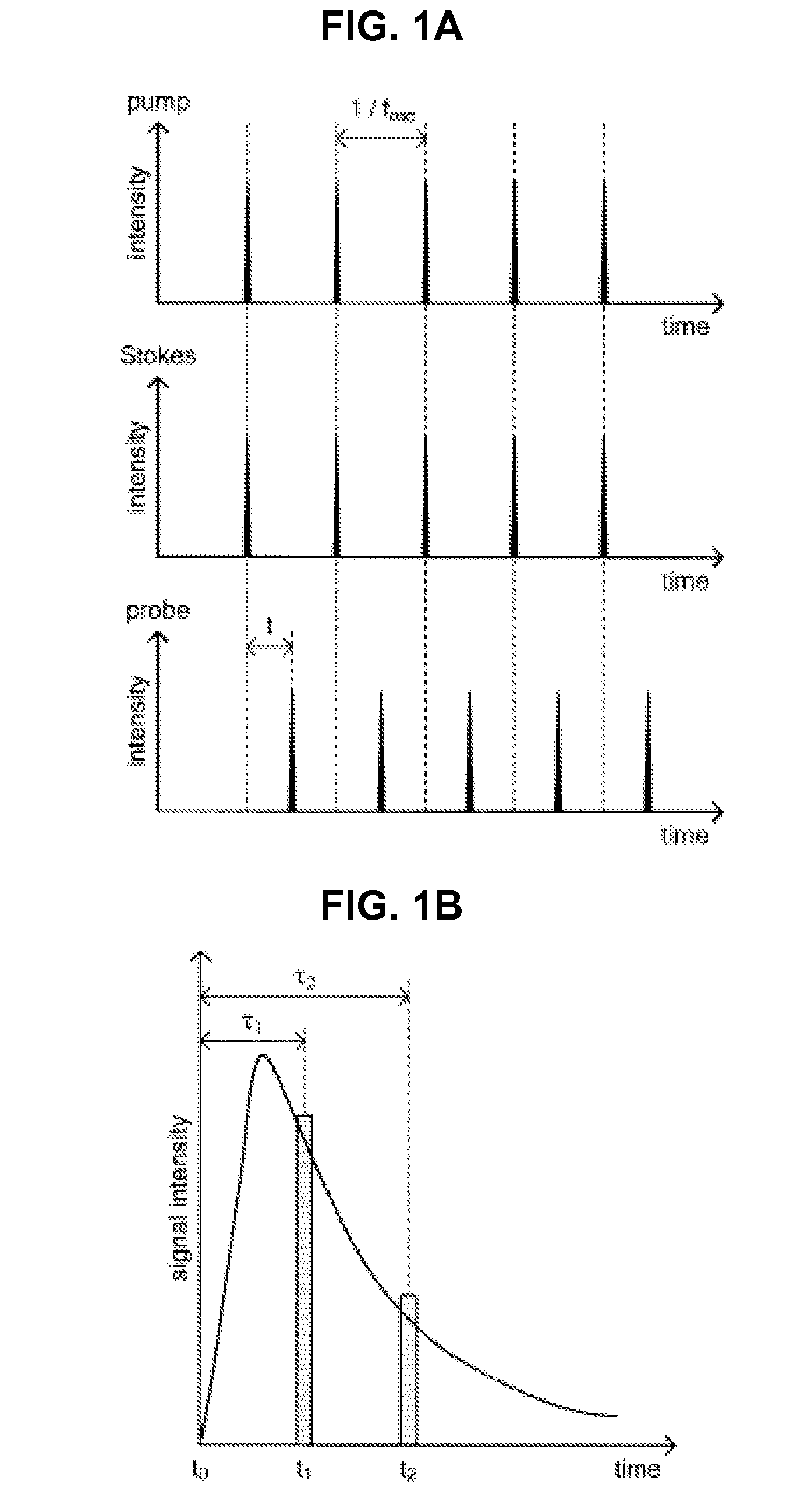
In the general Raman spectroscopy (in other words, a wavenumber domain), a reciprocal of a spectrum width derived from uniform broadening of a spectrum corresponds to a relaxation time, but high spectrum resolution is required, and thus measurement is difficult as described above.
However, in a relaxation time measurement method using the CARS, there is a problem in that decision of a relaxation time becomes difficult due to being affected by a non-resonant background.

Method used


Image

  • Measurement apparatus and measurement method
  • Measurement apparatus and measurement method
  • Measurement apparatus and measurement method

Examples


first embodiment

[0064]Next, the measurement apparatus and the measurement method according to a first embodiment of the present disclosure will be described in detail with reference to FIGS. 4 to 8.

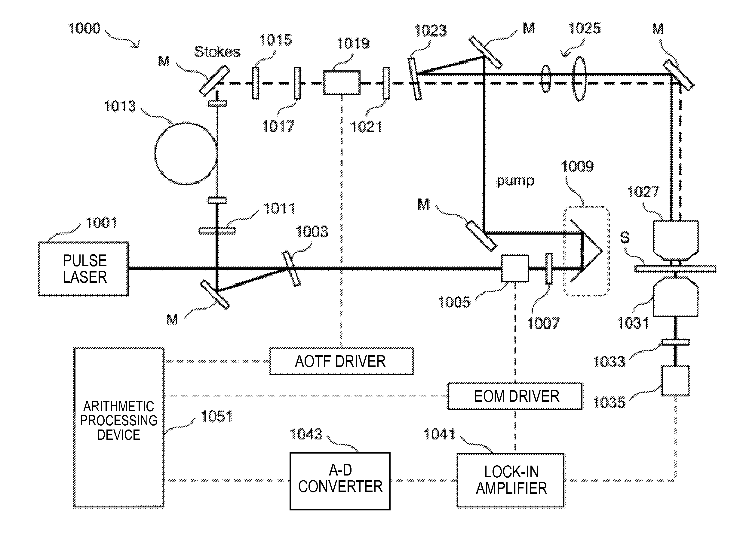
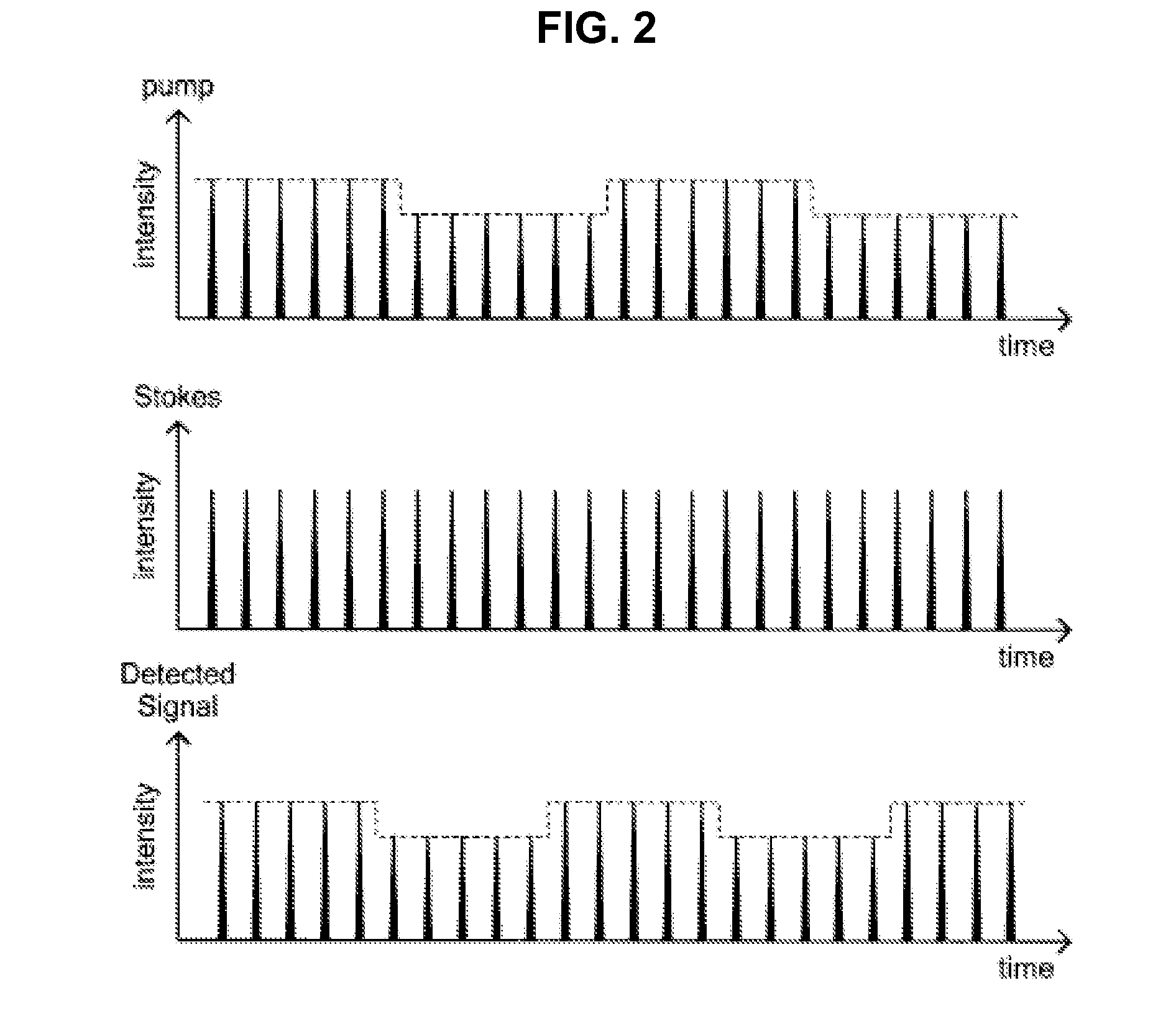
[0065]First, a configuration of the measurement apparatus that measures time-resolved stimulated Raman gain among measurement apparatuses according to the present embodiment will be described in detail with reference to FIGS. 4 to 6. FIG. 4 is an illustrative diagram for describing lock-in detection in a time-resolved stimulated Raman gain measurement apparatus according to the present embodiment. FIG. 5 is an illustrative diagram showing an example of a configuration of the time-resolved stimulated Raman gain measurement apparatus according to the present embodiment. FIG. 6 is a block diagram showing an example of a configuration of an arithmetic processing device included in the time-resolved stimulated Raman gain measurement apparatus according to the present embodiment.

[Overview of the Time-Resolved ...

second embodiment

[0158]In the measurement apparatuses according to the first embodiment described above, the intensity modulation process is performed only on the probe light. Here, by using a second reference frequency different from the first reference frequency that is used in performing intensity modulation on the probe light to perform intensity modulation on Stokes light and pump light, and then detecting the two kinds of pulsed light that have modulated with the two different reference frequencies, stimulated Raman scattered light can be measured at the same time in both cases in which time delay is performed and not performed. Accordingly, further speed-up of the measurement process can be achieved. Hereinbelow, measurement apparatuses according to a second embodiment of the present disclosure in which two kinds of pulsed light are modulated using two kinds of reference frequencies will be described in detail.

[0159]First, a configuration of a measurement apparatus that can measure time-resol...

modified example

[0214]The cases in which supercontinuum light from the non-linear optical fiber NFL is used as Stokes light have been described in the embodiments of the present disclosure described above, but in addition to the embodiments, a device configuration in which two Ti-sapphire ultrashort pulse lasers are synchronized to generate pump light, Stokes light, and probe light is also possible as shown in, for example, FIG. 14.

[0215]Note that an available pulse laser is not limited to the Ti-sapphire ultrashort pulse laser, and other kinds including a solid ultrashort pulse laser using crystal, a fiber ultrashort pulse laser, an optical parametric oscillator, and the like can be used.

[0216]FIG. 14 shows a device configuration in which Ti-sapphire ultrashort pulse lasers 511 and 513 having central wavelengths of 790 nm and 860 nm and pulse widths of 200 fs to 500 fs are used as a light source unit 511. In the present modified example, a phase-locked loop circuit (PLL circuit) 515 is used to cau...


PUM

PropertyMeasurementUnit
relaxation timeaaaaaaaaaa
time-aaaaaaaaaa
wavelengthaaaaaaaaaa

Abstract

There is provided a measurement apparatus including a light source unit configured to emit pulsed laser light used for pump light and Stokes light that excite predetermined molecular vibration of a measurement sample and for probe light that is intensity-modulated with a predetermined reference frequency and that has a same wavelength as the pump light or the Stokes light, a pulse control unit configured to cause time delay of the probe light generated by the light source unit and then to guide the pump light, the Stokes light, and the time-delayed probe light to the measurement sample, and a detection unit configured to detect transmitted light transmitted through the measurement sample or reflected light from the measurement sample. A relaxation time of the molecular vibration of the measurement sample is measured using time-resolved stimulated Raman gain spectroscopic measurement or time-resolved stimulated Raman loss spectroscopic measurement of the measurement sample.

Description

TECHNICAL FIELD[0001]The present disclosure relates to a measurement apparatus and a measurement method.BACKGROUND ART[0002]A vibration spectral region that is important in considering application of vibrational spectroscopy is in the range of 300 cm−1 to 3600 cm−1 that is known as a molecular fingerprint region. As a method for measuring a vibration spectrum corresponding to the region having these wavenumbers, an infrared spectroscopic method and a Raman spectroscopic method are representative methods, and by using both measurement methods, complementary information relating to molecular vibration of a sample can be obtained. Here, in the case of a sample such as a biological sample that contains water as a main ingredient, a vibration spectrum caused by water is observed in the infrared spectroscopic method, and thus the Raman spectroscopic method is mostly used.[0003]However, in analysis, examination, and diagnosis of a biological material, a Raman spectrum of the biological mat...

Claims


Application Information

Patent Timeline
Patent Type & Authority Applications(United States)
IPC IPC(8): G01N21/65
CPCG01N21/65G01J3/0208G01J3/0218G01J3/1256G01J3/44G01N2021/653G01N2021/655G01N2201/067
Inventor TAMADA, SAKUYA
Owner SONY CORP
Learn More